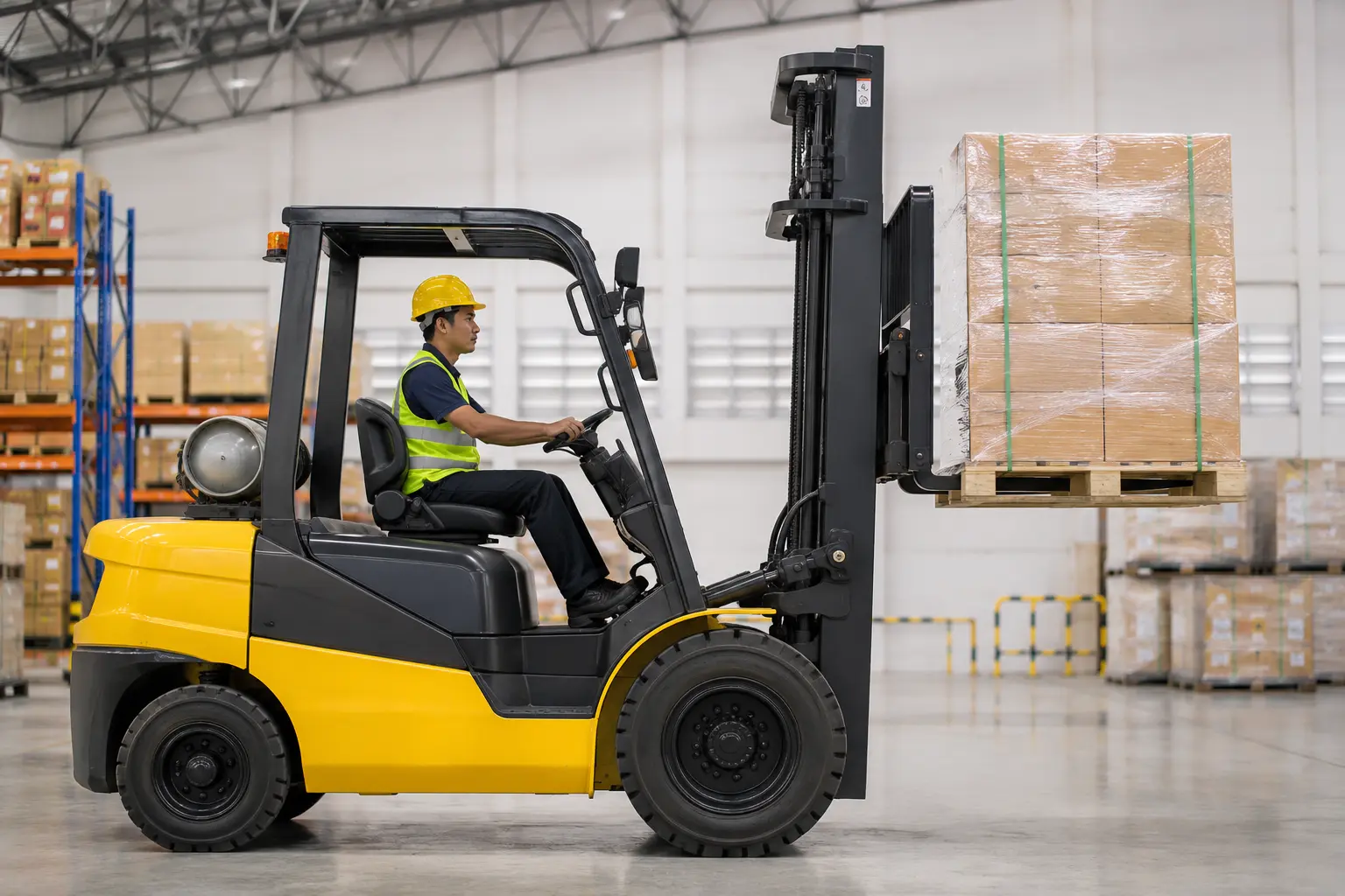
A forklift makes lifting several hundred kilograms off the ground look almost effortless, a smooth, controlled motion that operators perform dozens of times a shift without a second thought. Underneath that simplicity sits a genuinely elegant combination of hydraulic engineering and basic physics, a hydraulic lifting system doing the actual work, a counterbalancing principle keeping the whole machine from tipping over, and a mast and tilt mechanism translating vertical force into precise, controlled positioning.
Understanding how these systems function together explains not just how a forklift lifts a load, but why it is built the way it is, why capacity decreases as a load moves further from the machine, and why certain operating mistakes are considerably more dangerous than they might first appear. This guide breaks down the forklift mechanism piece by piece, from the hydraulic system that provides the lifting force through to the physics that keeps the whole machine stable while it works.
What Is the Forklift Mechanism?
The forklift mechanism refers to the combined hydraulic, mechanical, and structural systems that allow a forklift to lift, tilt, and transport a load safely. Rather than a single component, it is the interaction between several distinct systems working in coordination, the hydraulic pump and cylinders that generate lifting force, the mast that guides the fork carriage vertically, the tilt cylinders that angle the load for stability, and the counterweight that keeps the entire machine balanced throughout.
Every one of these systems depends on the others functioning correctly, a powerful hydraulic system means little without a mast structurally capable of guiding the load smoothly, and neither matters if the counterbalance principle underlying the whole machine is not respected during operation. A detailed look at the individual physical components that make up these systems is available in our guide to what each part of a forklift does, useful companion reading alongside this explanation of how those parts function together.
The Hydraulic Lifting System
At the core of every forklift’s lifting capability sits a hydraulic system, a closed network of fluid, pumps, valves, and cylinders that converts engine or battery power into the mechanical force needed to raise a load.
Hydraulic systems are used because they can generate enormous lifting force from a relatively compact and lightweight set of components, a property that would be far harder to achieve with a purely mechanical system of gears and cables at the same scale.
The Hydraulic Pump and Fluid Pressure

A hydraulic pump, driven by the forklift’s engine or electric motor, pressurises hydraulic fluid and directs it through a network of hoses toward the lift cylinders. When the operator engages the lift control, a valve opens to allow pressurised fluid into the cylinder, and this fluid pressure pushes a piston outward, generating the force that raises the forks.
Because hydraulic fluid is essentially incompressible, this system can hold a raised load steady with minimal drift, once the valve closes, the trapped fluid resists further movement, allowing a forklift to hold a load at height without the lift slowly sinking under its own weight.
Lift Cylinders and Chains
The main lift cylinder extends vertically within the mast, and rather than lifting the fork carriage directly, it is typically connected through a chain and pulley arrangement that doubles the effective travel of the carriage relative to the cylinder’s own extension. This chain-and-pulley system is why a forklift’s fork carriage can travel considerably higher than the hydraulic cylinder itself physically extends.
Chains in this system carry significant load and are subject to wear over time, which is why chain inspection and lubrication form a routine part of forklift upkeep, covered in more detail in Forklift Maintenance Tips for Safe and Efficient Operation, since a worn or poorly maintained lift chain represents a genuine safety risk given how much load it carries during normal operation.
Auxiliary Hydraulic Circuits
Beyond the main lift function, most forklifts include auxiliary hydraulic circuits that power the tilt cylinders and, where fitted, additional attachments such as side shifters, clamps, or rotators. These auxiliary circuits draw from the same pressurised fluid supply but are controlled independently, allowing the operator to lift, tilt, and operate an attachment through separate, dedicated controls.
Also read: Forklift Maintenance Tips for Safe and Efficient Operation
Counterbalance and Load Moment Physics
Perhaps the most important, and least visually obvious, part of the forklift mechanism has nothing to do with hydraulics at all, it is the physics of counterbalance that keeps the entire machine from tipping forward the moment it lifts a load.
A forklift’s forks extend forward of its front axle, which acts as a pivot point, meaning any load lifted creates a forward-tipping force around that axle exactly like a see-saw. Without something offsetting that force, the machine would simply tip forward the instant a load left the ground.
How the Counterweight Offsets Load
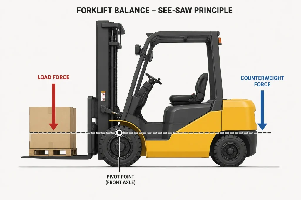
A heavy counterweight, usually a dense block of cast iron or concrete, is mounted at the rear of the forklift specifically to generate an opposing moment around the front axle, balancing the tipping force created by a load at the front. This is why the most common forklift configuration is specifically called a counterbalance forklift, its entire stability strategy depends on this rear weight rather than outriggers or a wider wheelbase.
The relationship between load and counterweight is precisely engineered rather than approximate, and a detailed breakdown of how this configuration works in practice, along with when it is the right choice compared to other forklift types, is available in Counterbalance Forklift: How It Works and When to Use It.
Load Centre and Why Capacity Decreases with Distance
A forklift’s rated capacity is always specified at a standard load centre, typically 500 millimetres from the face of the forks, the assumed distance from the fork face to a load’s centre of gravity. If a load’s actual centre of gravity sits further out than this standard distance, whether because the load itself is unusually long or is not pushed fully back against the fork carriage, the effective tipping moment increases even though the load’s actual weight has not changed.
This is why two loads of identical weight can represent very different levels of risk depending on their shape and how they are positioned on the forks, a compact, dense load sitting close to the mast is inherently more stable than the same weight in a long, awkward shape extending well beyond the standard load centre.
Also read: Counterbalance Forklift: How It Works and When to Use It
The Mast and Tilt Mechanism
The mast is the vertical guide rail structure the fork carriage travels along, and its design directly determines both how high a forklift can lift and how it behaves while doing so.
Single, Duplex, and Triplex Mast Stages
Masts are built from one, two, or three telescoping sections, referred to as single, duplex, and triplex configurations, each additional stage adding lift height without proportionally increasing the machine’s collapsed height. A triplex mast, for example, can reach considerably greater heights than a single-stage mast of the same collapsed height, since the additional telescoping sections extend well beyond where a simpler mast would stop.
This staged extension does introduce a trade-off, however, since more mast sections generally mean a narrower operator sightline through the mast structure at full extension, a factor that matters when specifying a forklift for a warehouse with particularly tall racking.
Tilt Cylinders and Load Stability
Separate hydraulic tilt cylinders angle the entire mast assembly backward and forward, and this tilt function serves a specific stability purpose rather than simply adjusting the fork angle for convenience. Tilting the mast backward while travelling with a raised load shifts the load’s weight closer to the machine’s centre, improving stability during transport, while forward tilt is used briefly during pickup and placement to align the forks with a pallet or load.
Operating with the mast tilted forward while travelling, rather than returning it to a backward tilt once a load is lifted, is one of the more common and avoidable ways operators unknowingly reduce their own stability margin during routine transport.
Steering and Drive Mechanism
Most forklifts steer using the rear wheels rather than the front, a configuration that feels counterintuitive to anyone used to a standard vehicle but that provides a significantly tighter turning radius, an important advantage in the narrow aisles typical of a warehouse environment.
Power to the drive wheels comes from either an internal combustion engine, in diesel and petrol models, or an electric motor drawing from an onboard battery, with the choice between these power sources covered in detail in Electric vs Diesel Forklifts: Which One Should You Choose?. Regardless of power source, the drive mechanism itself works independently of the hydraulic lifting system, meaning a fault in one system does not necessarily affect the other, though both draw on the same engine or battery as their ultimate power source.
Also read: Electric vs Diesel Forklifts: Which One Should You Choose?
How the Mechanism Works Together in Practice
Bringing these systems together, lifting a load with a forklift follows a consistent mechanical sequence: the operator drives forward until the forks are positioned beneath the load, tilts the mast slightly forward to align the forks with the pallet’s openings, drives fully in, then engages the lift function to raise the load while simultaneously tilting the mast backward to bring the load’s weight closer to the machine for stable transport.
Throughout this sequence, the counterbalance principle is working continuously in the background, the hydraulic system is holding the raised load steady through trapped fluid pressure, and the mast structure is guiding the fork carriage precisely along its vertical path. None of these systems function in isolation, and understanding how they interact is genuinely useful background for operators, since it explains why specific practices, keeping loads within the rated load centre, tilting back during transport, avoiding travel with the mast raised, exist as mechanical necessities rather than arbitrary rules. Broader forklift classification, including how mechanism differs across counterbalance, reach truck, and other configurations, is covered in Classes of Forklifts and Their Uses in Material Handling. Further general technical background on forklift design and history is available through Wikipedia’s overview of forklifts.
Understanding the Machine You Operate
A forklift’s mechanism is a genuinely elegant piece of engineering, a hydraulic system generating lifting force, a mast guiding that force precisely along a vertical path, and a counterbalance principle keeping the whole assembly stable throughout. Understanding how these systems work together, rather than simply which lever does what, is what allows an operator to work safely and a business to specify the right machine for a given task.
RR Machinery Pte Ltd offers a diverse selection of well-maintained forklifts suited to every application and budget. Contact us today for expert advice on the right forklift mechanism and configuration for your operations.