Forklifts are among the most widely used pieces of material handling equipment in warehouses, construction sites, logistics facilities, and industrial operations. Yet despite their prevalence, a detailed understanding of forklift components, what each part is called, what it does, and how it contributes to the machine’s overall function, is less common than it should be among the people who operate, maintain, and manage them.
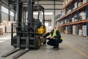
Understanding the parts of a forklift matters for several practical reasons. Operators who know their machine’s components can identify problems earlier, communicate more accurately with technicians, and operate with a better understanding of the mechanical forces at work during lifting. Maintenance teams benefit from a shared vocabulary that reduces miscommunication and speeds up diagnosis. Fleet managers and procurement teams need component knowledge to evaluate service agreements, assess repair estimates, and make informed decisions about equipment replacement.
Whether you work with diesel forklifts on a construction site, electric forklifts in a warehouse, or LPG models in an industrial facility, the core components are largely the same. This guide covers all the main parts of a forklift, grouped by their function, with a clear explanation of what each component does and why it matters for safe, efficient operation.
Main Structural Parts of a Forklift
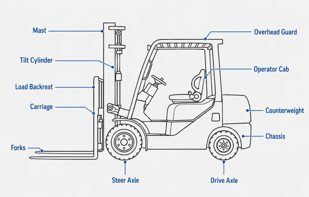
The structural framework of a forklift gives the machine its shape, provides the mounting points for all operational components, and transfers loads safely between the lifting mechanism and the ground.
Chassis (Frame)
The chassis, also called the frame, is the main structural body of the forklift. It is the rigid, welded steel structure that everything else is mounted to: the mast, the engine or battery compartment, the counterweight, the operator’s compartment, and the axles. The chassis must be strong enough to withstand the static and dynamic loads generated during lifting, travel, and turning, including the significant torsional forces that occur when the machine turns while carrying a load.
The chassis design also determines the forklift’s centre of gravity, which is critical to its stability. A low, wide chassis improves stability but may limit manoeuvrability in tight spaces. Understanding how chassis geometry affects stability is as fundamental to forklift safety as understanding the load chart, and both are considerations that experienced material handling equipment operators and fleet planners pay close attention to when selecting equipment for a given facility.
Counterweight
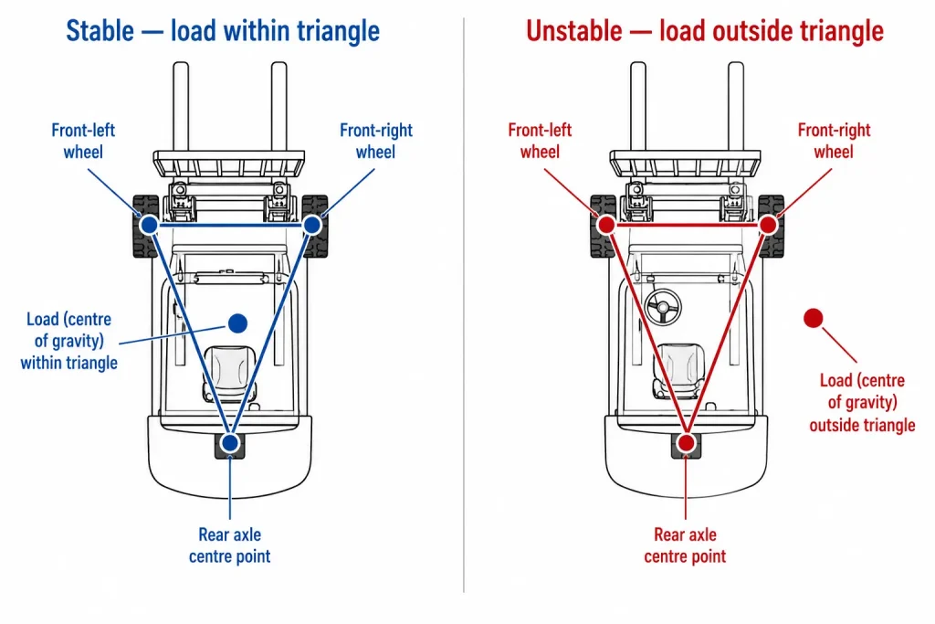
The counterweight is a heavy cast iron or steel block mounted at the rear of the forklift, opposite the forks. Its purpose is to balance the load being carried at the front of the machine. Without a counterweight, a loaded forklift would tip forward over its front axle, the counterweight provides the rearward moment that keeps the machine stable during lifting and travel.
The counterweight is sized by the manufacturer based on the forklift’s rated capacity. It is not adjustable in the field. Operators who exceed the rated load capacity effectively overpower the counterweight’s stabilising effect, creating a tip-over risk that is one of the most common causes of serious forklift accidents.
Overhead Guard (ROPS)
The overhead guard, sometimes called the operator guard or ROPS (Roll-Over Protective Structure), is the steel frame structure above the operator’s seat. Its primary function is to protect the operator from falling objects dislodged from loads or racking, and to provide structural protection in the event of a tip-over. The overhead guard is not designed to withstand the impact of very heavy falling loads, but it provides critical protection against the most common overhead hazards on a warehouse or site floor.
In Singapore, overhead guards are a mandatory safety requirement on all forklifts used in workplaces regulated by the Workplace Safety and Health (WSH) Act.
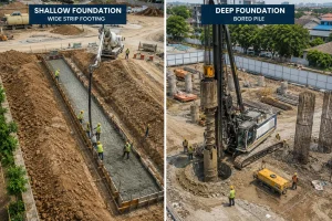
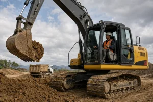
Also read : Types of Excavator Buckets and Their Uses Explained
The Mast and Lifting Components
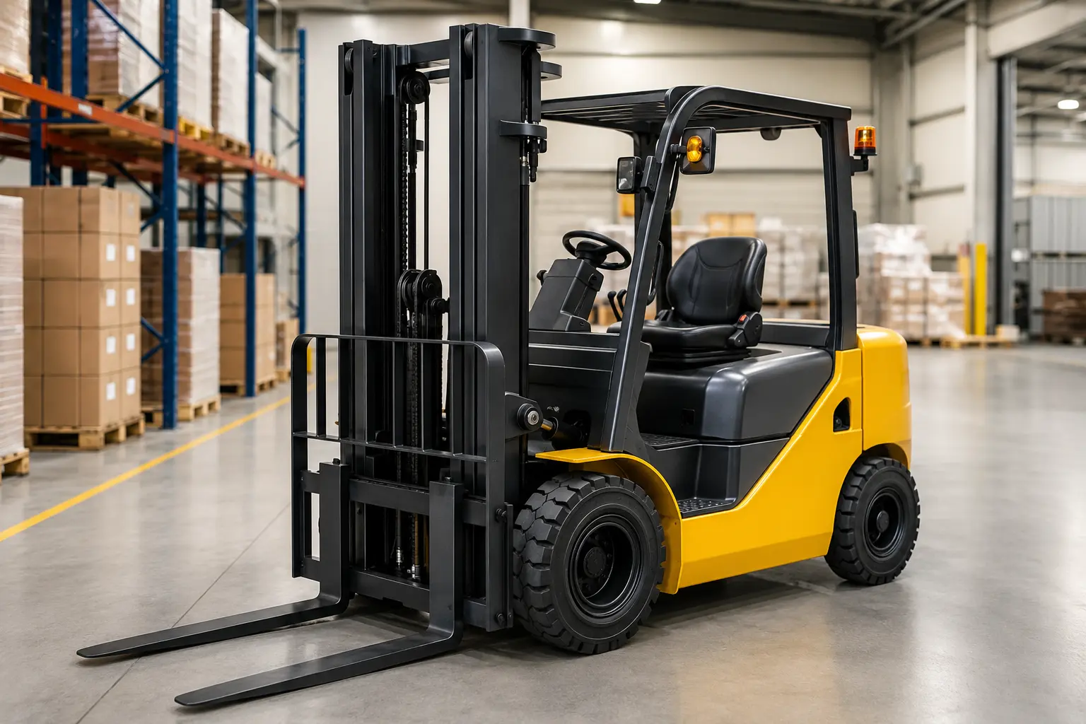
The mast assembly is the most visually prominent part of a forklift and the mechanism directly responsible for raising, lowering, and tilting the load.
Mast
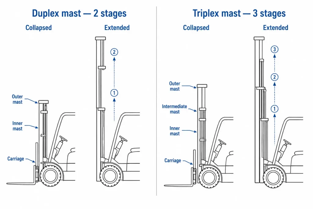
The mast is the vertical assembly at the front of the forklift through which the forks are raised and lowered. It consists of interlocking steel rails, called channels, that slide within each other to achieve lift height. Most forklifts use a two-stage or three-stage mast:
A two-stage mast (duplex mast) uses two sets of channels. The inner channel rises within the outer channel to achieve the rated lift height. This configuration provides good visibility through the mast and is common in lower-lift applications.
A three-stage mast (triplex mast) uses three sets of channels. The two inner channels rise sequentially within the outer channel, allowing the mast to achieve significantly greater lift heights while keeping the collapsed height of the mast relatively compact. Triplex masts are the standard choice for high-rack warehouse operations where the forklift must pass through doorways or under overhead obstacles while still reaching elevated rack positions.
The mast is powered by hydraulic cylinders, typically one or two primary cylinders that extend to raise the inner channels, plus free-lift cylinders that raise the carriage before the mast begins to extend.
Free Lift
Free lift refers to the amount the forks and carriage can be raised before the mast channels begin to extend upward. In a mast with good free lift, the forks can be raised to a useful working height, for example, high enough to place a load on a raised platform, without increasing the overall height of the mast above the operator’s head. This is critical for operations in buildings with restricted overhead clearance, such as shipping containers, vehicles, and low-ceiling warehouses.
Carriage
The carriage is the rectangular steel frame that travels up and down the mast rails. The forks, and any fork attachments, are mounted directly to the carriage. The carriage also carries the backrest extension (load backrest) that prevents the load from sliding backward off the forks during lifting and transport.
Carriages are standardised according to width classes (Class I through Class V) defined by the FEM/ISO standard, which determines which fork attachments are compatible with which forklifts.
Forks (Tines)
The forks, also called tines, are the two L-shaped steel prongs that extend horizontally from the carriage and insert beneath the load or into the pockets of a pallet. They are the most visible and most purpose-critical part of the forklift: every lift begins and ends with the forks engaging the load correctly.
Forks are manufactured from high-strength steel and are subject to wear and fatigue over time. Forklift safety standards, including those endorsed by Singapore’s MOM, require forks to be inspected regularly for cracks, bending, wear at the heel (the inner bend of the fork), and dimensional deformation. Forks that show wear beyond defined limits must be replaced, not repaired by welding, as welding compromises the metallurgical properties of the steel.
Fork width spacing is adjustable on most forklifts to accommodate different pallet sizes. Operators should always ensure the forks are positioned as wide as practical for the load being handled to maximise stability.
Tilt Cylinders
The tilt cylinders are hydraulic cylinders mounted on each side of the mast that allow the entire mast, and therefore the forks, to tilt forward and backward relative to the chassis. Most forklifts tilt between 3 and 6 degrees forward (to facilitate load engagement and deposit) and 3 to 12 degrees backward (to secure the load against the backrest during travel).
Tilting the forks fully backward during travel is a fundamental safety practice: it keeps the load close to the mast, lowers the combined centre of gravity of the machine and load, and reduces the risk of the load sliding forward off the forks on ramps or during braking.
Load Backrest Extension
The load backrest extension, sometimes called the fork backrest, is a vertical steel plate mounted on the upper portion of the carriage, behind the fork tips. Its function is to provide a rear stop for the load when the forks are elevated and tilted back, preventing pallets or boxes from sliding backward into the operator’s area. It does not replace proper load securing, but it provides a critical mechanical backstop for normal operations.
Hydraulic System Components
The hydraulic system generates, stores, and distributes the pressurised fluid that powers the mast lift cylinders, tilt cylinders, and any hydraulic attachments.
Hydraulic Pump
The hydraulic pump draws fluid from the reservoir and pressurises it, supplying the force needed to extend the lift cylinders and tilt the mast. On engine-powered forklifts, the hydraulic pump is driven mechanically by the engine. On electric forklifts, it is driven by a dedicated electric motor.
Pump condition directly affects lift performance. A worn pump produces lower hydraulic pressure, resulting in slower lift speeds, reduced maximum lift capacity, and in severe cases, inability to raise loads to full height. Regular hydraulic fluid maintenance, including fluid changes and filter replacement on schedule, is the most important factor in preserving pump life.
Hydraulic Control Valves
The control valves regulate the flow of hydraulic fluid to each cylinder, the lift cylinder, the tilt cylinders, and any auxiliary circuits for attachments. The operator controls these valves directly through the hydraulic control levers in the cab. Each lever position corresponds to a specific valve position: raise, lower, tilt forward, tilt back, or attachment function.
Modern electric forklifts increasingly use electro-hydraulic controls, joysticks or touchpad controls that send electrical signals to solenoid-operated valves rather than directly actuating the valves through mechanical linkage. This improves precision and allows programmable performance settings.
Hydraulic Reservoir and Filter
The hydraulic reservoir stores the hydraulic fluid used by the system. Most forklifts carry between 20 and 60 litres of hydraulic fluid depending on their size. The reservoir is fitted with a filter that removes contaminating particles before fluid enters the pump and valves. Contaminated hydraulic fluid is a leading cause of premature pump and valve wear, maintaining clean fluid and replacing the filter on schedule is essential for hydraulic system longevity.
Also read : Construction Equipment Names: A Complete Reference Guide
Powertrain and Engine Components
The powertrain converts fuel or electrical energy into the mechanical power needed to drive the forklift and operate the hydraulic system.
Engine (Internal Combustion Models)
Diesel, LPG, and gasoline forklifts use an internal combustion engine to generate power. The engine drives both the forklift’s travel (through the transmission and drive axle) and the hydraulic pump (through a power take-off). Engine displacement, power output, and torque characteristics determine how the forklift handles heavy loads, ramps, and sustained duty cycles.
Diesel engines are the most common in heavy industrial and outdoor forklifts due to their fuel efficiency, durability, and suitability for sustained heavy use. LPG engines offer lower emissions and quieter operation, making them a practical alternative for indoor facilities with some ventilation. The full range of available fuel types and configurations across different forklift models is covered in detail in our guide on forklift types and their applications.
Electric Motor and Battery (Electric Models)
Electric forklifts replace the combustion engine with one or more electric motors powered by a large lead-acid or lithium-ion battery pack. The battery, typically mounted low in the chassis to lower the centre of gravity and improve stability, provides power for both drive and hydraulic functions. Battery capacity is rated in kilowatt-hours (kWh) and determines how long the forklift can operate between charges.
Electric forklifts produce zero direct emissions and significantly lower noise levels than combustion models, making them the standard choice for food processing, pharmaceutical, cold storage, and other indoor environments with strict air quality or noise requirements. Their lower running costs and reduced maintenance requirements compared to engine-powered forklifts have made them increasingly common across a wide range of Singapore warehouse and logistics operations.
Transmission
The transmission transfers power from the engine or drive motor to the drive axle, controlling the forklift’s travel speed and direction. Most forklifts use a hydrostatic transmission, a hydraulic circuit that connects the engine to the drive wheels, rather than a conventional mechanical gearbox. Hydrostatic transmissions provide smooth, stepless speed control and allow the direction of travel to be reversed instantly without a clutch, which is important for the frequent directional changes typical of warehouse operations.
Drive Axle and Steer Axle
Most counterbalance forklifts are driven through the front axle (closest to the mast) and steered through the rear axle. This rear-wheel steering arrangement is the opposite of most road vehicles and is one of the most important handling characteristics for new operators to understand. Because the rear of the forklift swings outward during turns, operators must account for the tail swing when manoeuvring in tight spaces, failure to do so is a common cause of collisions with racking, walls, and pedestrians.
Operator Controls and Safety Components
The operator’s compartment houses all the controls the driver uses to operate the forklift, along with the safety systems that monitor machine condition and protect against unsafe operation.
Steering Wheel and Hydraulic Controls
The steering wheel controls the steer axle via a hydraulic or electric power steering system. The hydraulic control levers, or joystick controls on modern electric models, operate the mast lift, tilt, and any attachment functions. On most forklifts, the hydraulic controls are positioned to the right of the operator and can be reached without removing the hand from the armrest.
Accelerator, Brake, and Inching Pedal
The accelerator controls travel speed. The brake pedal applies the service brakes. The inching pedal, a feature found on most internal combustion forklifts, allows the operator to disengage the transmission gradually without stopping the engine, enabling the operator to increase engine speed (and therefore hydraulic pressure for lifting) while keeping travel speed low. This is particularly useful when engaging loads on ramps or picking from very low pallet positions.
Parking Brake
The parking brake locks the forklift stationary when it is not in use. On most forklifts, it is applied by a hand lever and must be engaged whenever the operator leaves the seat. Failure to apply the parking brake on a slope is a common cause of runaway forklift incidents.
Seat and Operator Presence System
The operator seat is fitted with a presence sensor, sometimes called a deadman switch, that detects whether an operator is seated. If the operator leaves the seat without engaging the parking brake, the presence system automatically cuts power to the drive and hydraulic circuits, preventing unintended movement. This system is a fundamental safety feature required on all modern forklifts under international safety standards.
Load Moment Indicator and Data Display
Modern forklifts are increasingly equipped with digital displays showing load weight, battery state of charge (electric models), operating hours, fault codes, and performance data. Some models include load moment indicators that warn operators when the load approaches the rated capacity limit at a given lift height and mast extension. These systems mirror the load monitoring technology found in other types of lifting equipment, including the load moment indicators fitted to crane systems used in heavy construction operations.
Tyres and Undercarriage
Pneumatic Tyres
Pneumatic tyres, air-filled tyres similar to those on road vehicles, are fitted to forklifts designed for outdoor use on rough or uneven surfaces. They provide cushioning over irregularities and better traction on unpaved or wet ground. Solid pneumatic tyres (also called cushion pneumatics) have the external profile of pneumatic tyres but are made from solid rubber, eliminating the risk of punctures while maintaining the larger diameter needed for outdoor terrain.
Cushion Tyres
Cushion tyres are solid rubber tyres mounted directly on the wheel rim with a smaller diameter than pneumatic alternatives. They are designed for smooth, hard indoor floors, concrete warehouse floors, factory floors, and loading docks. Cushion-tyred forklifts sit lower than pneumatic models, giving them a lower centre of gravity and improved stability for high-lift operations in controlled environments. They should not be used on unpaved surfaces, ramps with poor surface quality, or outdoor terrain.
Why Understanding Forklift Components Matters?
Knowing the parts of a forklift, from the chassis and counterweight through to the hydraulic system, mast assembly, and operator safety controls, builds the foundation for safer and more effective operation. Operators who understand what each component does are better equipped to spot developing problems before they become failures, communicate accurately with maintenance teams, and apply the correct techniques when handling different load types and site conditions.
For businesses managing a forklift fleet, component knowledge also informs better maintenance scheduling, more accurate service cost forecasting, and smarter decisions about when repair is economical versus when replacement is the more cost-effective option. These considerations apply equally when comparing forklift capabilities against other material handling solutions for a given operation.
For technical reference on forklift engineering principles, international safety standards, and load capacity calculation methods, resources on industrial forklift mechanics and safety regulations provide useful background on how component design standards are determined and applied across different jurisdictions.
Also read : How Does a Generator Work? Principles, Components, and Types Explained
Get the Right Forklift for Your Operation
Understanding the parts of a forklift gives operators, maintenance teams, and fleet managers a clearer picture of how the machine works, what keeps it safe, and what needs attention when performance changes. Every component, from the counterweight and mast assembly to the hydraulic system and operator controls, plays a specific role in making the forklift a reliable, efficient, and safe piece of equipment in your operation.
RR Machinery offers a comprehensive range of forklifts for sale and rental across Singapore, including diesel, electric, and LPG models in a wide range of lifting capacities. Every unit is professionally maintained and supported by factory-certified technicians providing both in-house and on-site service. Explore our full range of forklift solutions for sale and rental, or contact our team for practical advice and a clear quotation tailored to your specific requirements.