
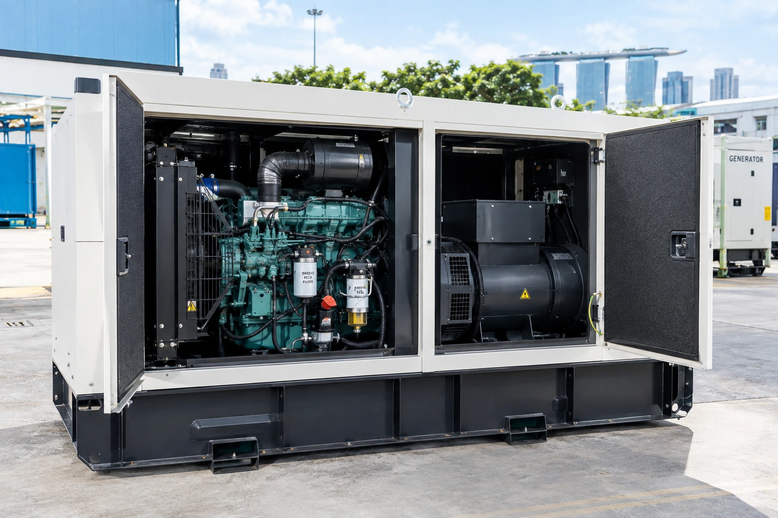
A generator is often described as a single unit, but it is really an assembly of several distinct subsystems working together, an engine to provide motion, an alternator to convert that motion into electricity, and a collection of supporting systems that keep the whole assembly fuelled, cooled, monitored, and protected. Knowing what each part actually does makes pre-use inspection more meaningful, helps with interpreting a fault when something goes wrong, and makes conversations with a technician considerably more productive.
This guide catalogues the individual components that make up a typical generator, organised by the subsystem each one belongs to, from the engine block through to the frame and enclosure that holds everything together. Understanding these components individually also builds a genuinely useful foundation for anyone responsible for specifying, operating, or maintaining a generator on a regular basis.
The Engine: The Generator’s Prime Mover
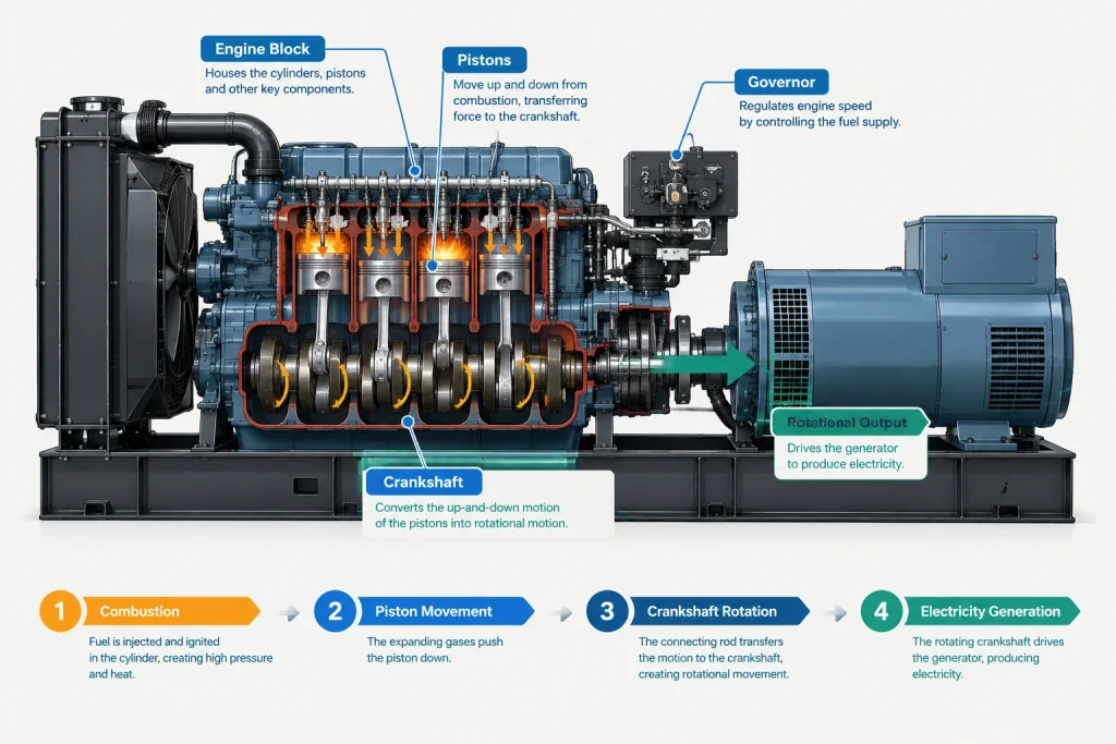
The engine is the component that starts the entire energy conversion process, burning fuel to produce the rotational motion every other part of the generator ultimately depends on.
Engine Block, Pistons, and Crankshaft
The engine block houses the pistons, which move up and down as fuel combusts within each cylinder, driving a crankshaft that converts this reciprocating motion into the rotational motion the alternator requires. This is the same fundamental combustion process used in most vehicle engines, adapted here to run at a constant speed rather than a variable one, since the alternator depends on stable rotational speed to produce electricity at the correct frequency. Most generator engines are also built for continuous duty rather than the intermittent stop-start use a road vehicle typically experiences, with correspondingly heavier-duty internal components designed to withstand sustained running hours.
Governor
The governor regulates fuel delivery to maintain a constant engine speed regardless of how much electrical load is applied, since a generator’s output frequency depends directly on how fast the engine spins. Without a functioning governor, engine speed would fluctuate as load changes, causing the generator’s output frequency to drift and potentially damaging sensitive equipment connected to it.
The Alternator: Where Motion Becomes Electricity
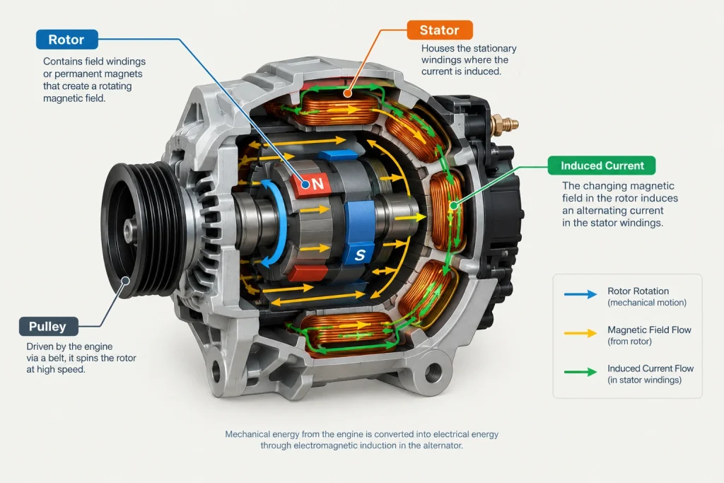
The alternator converts the engine’s rotational motion into electrical current through electromagnetic induction, the same basic physical principle used in generators of every size and configuration.
Rotor and Stator
The rotor, connected directly to the engine’s crankshaft, spins within the stator, a stationary assembly of copper windings, and this relative motion between a magnetic field and the copper windings is what induces an electrical current. The specific arrangement and quality of these windings directly affects the alternator’s output capacity and efficiency, making this one of the more expensive components to replace if it fails. Insulation quality around these windings also matters considerably for long-term reliability, since heat and moisture exposure over years of service gradually degrade insulation in ways that eventually lead to a short circuit if left unaddressed.
Automatic Voltage Regulator
The automatic voltage regulator, or AVR, continuously monitors output voltage and adjusts the current supplied to the rotor’s field winding to keep voltage stable as electrical load changes throughout operation. A closer look at how the AVR and governor work together to keep both voltage and frequency stable under changing load is available below, useful reading for understanding the full control logic these components participate in.
Also read: Inside a Generator: The Mechanism That Keeps Power Stable
Fuel System Components
The fuel system stores fuel and delivers it to the engine at the pressure and rate combustion requires, a straightforward-sounding job that still involves several distinct parts working correctly together.
The fuel tank stores the generator’s onboard fuel supply, sized according to the unit’s class and intended runtime, while fuel lines carry fuel from the tank to the engine, passing through a fuel filter along the way that removes contaminants before they can reach and damage sensitive engine components. On diesel units, fuel injectors deliver a precisely metered, high-pressure spray of fuel directly into each cylinder at exactly the right moment in the combustion cycle, a level of precision that directly affects both fuel efficiency and engine performance. Handling fuel safely during refuelling, including switching off the engine and letting it cool first, is one of several practical safety habits covered in Generator Safety Tips Every Operator Should Know.
Cooling and Exhaust Components
An engine running continuously generates substantial heat, and the cooling system exists specifically to remove that heat before it damages engine components or causes a shutdown.
Most generators use a radiator and coolant circulation system similar in principle to a vehicle’s cooling system, with a fan drawing air across the radiator to dissipate heat carried away from the engine block by circulating coolant. The exhaust system carries combustion gases safely away from the engine and typically includes a muffler that reduces the noise these gases would otherwise produce, a component that matters considerably more for the enclosed, sound-attenuated units covered below, where exhaust noise reduction is engineered specifically into the design.
Control Panel and Monitoring Components
The control panel is where an operator interacts with the generator directly, providing both the controls needed to start and stop the unit and the instrumentation needed to monitor its condition while running.
A typical control panel displays voltage, frequency, and running hours at minimum, with more sophisticated panels adding fuel level, oil pressure, and coolant temperature readouts that allow a developing problem to be caught before it causes a shutdown. Standby generators typically also include an automatic transfer switch interface, the component that detects a mains power failure and triggers the generator to start and connect to a building’s electrical circuits without manual intervention. Knowing how to read these instruments correctly during the actual starting and shutdown sequence is covered step by step in How to Use a Generator: A Step-by-Step Guide. Many modern control panels also include remote monitoring capability, allowing fuel level, running status, and fault codes to be checked without physically visiting the generator’s location.
Frame, Enclosure, and Base
The frame or base holds every other component together as a single, transportable unit, while an enclosure, where fitted, wraps around the engine and alternator for weather protection, noise reduction, or both.
A skid base or wheeled frame provides the structural foundation the engine, alternator, and fuel tank all mount to, engineered to absorb the vibration a running engine produces without transmitting excessive noise or movement to the surrounding structure. Where a full enclosure is fitted, it typically incorporates the same sound-dampening insulation and baffled ventilation covered in the silent versus open generator comparison referenced above, since the enclosure itself is what actually achieves a silent generator’s noise reduction.
How These Parts Work Together
A generator functions as a coordinated system rather than a collection of independent parts, the engine burns fuel to produce rotational motion, the governor keeps that motion at a constant speed, the alternator converts the motion into electrical current, the AVR keeps that current’s voltage stable, and the fuel, cooling, and exhaust systems keep the whole assembly running safely and continuously throughout. A fault in any single component, a clogged fuel filter, a failing AVR, a blocked radiator, affects the performance of the entire system rather than just the immediate part involved, which is why understanding each component individually matters for genuinely effective inspection and troubleshooting.
Understanding how these same components combine into the complete package referred to as a genset, and the terminology used across technical specification sheets, is covered below. Further general technical background on generator and alternator design is available through Wikipedia’s overview of electric generators.
Also read: What Is a Genset? Understanding the Generator Set
Understanding the Machine You Rely On
Knowing what each generator component does, the engine and governor that produce stable rotational motion, the alternator and AVR that convert and regulate electrical output, and the fuel, cooling, and control systems that keep everything running safely, gives operators and site managers a genuinely useful frame of reference for inspection, troubleshooting, and communicating with maintenance staff when something needs attention. This same component knowledge also makes it considerably easier to recognise a developing issue early, before a minor wear pattern becomes a costly failure during an actual power outage.
RR Machinery Pte Ltd offers a wide selection of power generators, professionally maintained and tested before every delivery. Contact us today for expert advice on the right generator for your power needs.