
A generator that is correctly sized for its load runs efficiently, reliably, and within its rated parameters for the full duration of the project it serves. A generator that is undersized trips under peak load, fails to start large motors, and causes operational disruption at the worst possible moment. A generator that is significantly oversized runs inefficiently at low load, accumulates engine deposits through wet stacking in diesel units, and costs more in fuel and capital than the application requires.
The difference between all three outcomes is the load calculation, the systematic process of establishing exactly how much electrical power the generator must supply, in what form, and under what operating conditions. Load calculation is not estimation and it is not guesswork. It is a structured technical process that, when carried out correctly, produces a precise minimum generator specification that eliminates both undersizing and unnecessary oversizing.
This guide sets out the complete load calculation process step by step, the electrical units involved, the method for establishing running loads and starting loads, the application of power factor and demand factor, the sizing margins that ensure reliable operation, and the common errors that produce inaccurate results. It applies to any generator application: construction site prime power, standby power for a building or facility, event temporary power, or industrial process power.
The Electrical Units You Need to Understand
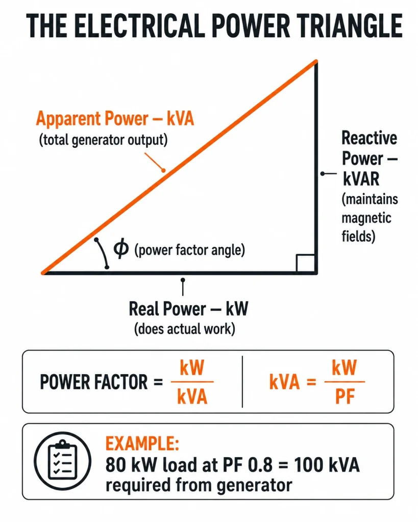
Accurate load calculation requires a working understanding of four electrical units. Confusion between these units, particularly between kilowatts and kilovolt-amperes, is the most frequent source of generator sizing errors.
- Watt (W) and kilowatt (kW)
The watt is the unit of real power, the power that performs actual work, such as heating, lighting, or driving a motor shaft. One kilowatt equals 1,000 watts. Equipment nameplates and data sheets typically express power consumption in watts or kilowatts.
- Kilovolt-ampere (kVA)
The kilovolt-ampere is the unit of apparent power, the total power that must be supplied by the generator, including both real power and reactive power. Generators are rated in kVA because they must supply apparent power to the load, not just real power. A generator’s kVA rating is always equal to or greater than its kW rating.
- Power factor (PF)
The ratio of real power to apparent power, expressed as a decimal between 0 and 1. The relationship is: kW = kVA × power factor. A purely resistive load, a heating element, an incandescent light, has a power factor of 1.0. An inductive load, an electric motor, a transformer, a welding machine, has a power factor below 1.0, typically between 0.7 and 0.9. Most generator specifications assume a power factor of 0.8.
- Reactive power (kVAR)
The component of apparent power that does not perform useful work but must still be supplied by the generator to maintain the electromagnetic fields in inductive loads. Reactive power is not directly relevant to most field load calculations, but understanding that it exists, and that it is the reason kVA is always greater than kW for inductive loads, is important for applying power factor correctly.
These four units are governed by the power triangle relationship: kVA² = kW² + kVAR². For practical load calculation, the key equation to apply at every step is: kW = kVA × PF, or rearranged: kVA = kW ÷ PF.
Also read : Diesel vs Petrol Generator: Which One Should You Choose?
How to Calculate Generator Load
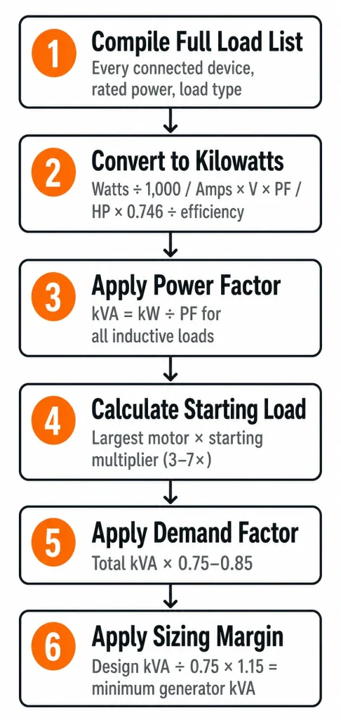
The load calculation process follows six sequential steps. Each step builds on the previous one, and the output of each step feeds into the next. Complete each step before proceeding.
Compile the Full Load List
List every piece of electrical equipment that will be connected to the generator simultaneously during normal operation. Every load matters, including loads that appear minor but run continuously.
For each item on the list, record:
The equipment name and description. Sufficient detail to identify the equipment and confirm its power specification, not just “pump” but “dewatering pump, 5.5 kW, 415V three-phase.”
The rated power consumption. From the equipment nameplate, data sheet, or manufacturer’s specification. Express in watts or kilowatts. If the nameplate shows amps rather than watts, note the voltage and the number of phases for conversion in Step 2.
The load type. Resistive (heaters, lights, computers) or inductive (motors, compressors, transformers, welding equipment). Load type determines the power factor applied in Step 3 and the starting current factor applied in Step 4.
Whether the load is continuous or intermittent. A continuously running load, a dewatering pump, site lighting, is present throughout the operating period. An intermittent load, a power tool, a concrete mixer used in batches, runs only during active use.
Do not omit loads because they seem small. A site office with computers, monitors, a kettle, a microwave, and a small air conditioning unit may draw 4 to 6 kW continuously. Omitting it from the calculation introduces a 4 to 6 kW error before any other calculation is made.
Convert All Loads to Kilowatts
Convert every load on the list to a kilowatt figure for calculation.
From watts: Divide by 1,000. A 1,500 W angle grinder = 1.5 kW.
From amps (single-phase): Apply the formula kW = (V × A × PF) ÷ 1,000. For a single-phase 230V motor drawing 10A at 0.85 power factor: kW = (230 × 10 × 0.85) ÷ 1,000 = 1.955 kW.
From amps (three-phase): Apply the formula kW = (√3 × V × A × PF) ÷ 1,000, where √3 = 1.732. For a three-phase 415V motor drawing 15A at 0.85 power factor: kW = (1.732 × 415 × 15 × 0.85) ÷ 1,000 = 9.17 kW.
From horsepower: Apply the conversion 1 hp = 0.746 kW, then divide by the motor efficiency to get electrical input power. A 10 hp motor with 90 percent efficiency draws 10 × 0.746 ÷ 0.90 = 8.29 kW electrically.
Record the kilowatt figure for each item. At the end of this step, every item on the load list has a kW value.
Apply Power Factor to Each Inductive Load
For each inductive load on the list, motors, compressors, transformers, calculate the kVA demand by dividing the kW figure by the power factor: kVA = kW ÷ PF.
If the power factor of a specific piece of equipment is not known from its data sheet, use the following default values:
- Electric motors (general): PF = 0.85
- Air conditioning and refrigeration compressors: PF = 0.75 to 0.85
- Welding equipment: PF = 0.70 to 0.80
- Fluorescent and LED lighting with electronic ballast: PF = 0.90 to 0.95
- Resistive loads (heaters, incandescent lights): PF = 1.0
For a 9.17 kW motor at PF 0.85: kVA = 9.17 ÷ 0.85 = 10.79 kVA.
The kVA figure, not the kW figure, is what the generator must supply for inductive loads. Record the kVA alongside the kW for each inductive load.
Also read : Heavy Equipment Safety: A Complete Site Guide
Calculate Starting Load for Motor Loads
Every electric motor draws a starting current significantly higher than its running current, typically three to seven times the full-load running current, for the first few seconds of starting as the motor accelerates to operating speed. During these seconds, the generator must supply the full starting kVA without the voltage dropping below acceptable limits for other equipment running on the system.
The starting kVA for a motor is calculated as: Starting kVA = Running kVA × Starting current multiplier.
Starting current multipliers by motor starting method:
- Direct-on-line (DOL) start: 5 to 7 × running current
- Star-delta start: 2 to 3 × running current
- Soft starter: 1.5 to 2.5 × running current
- Variable frequency drive (VFD): 1.0 to 1.5 × running current
For the 10.79 kVA motor above, starting DOL: Starting kVA = 10.79 × 6 = 64.7 kVA.
Identify the single largest motor starting kVA on the load list, this is the peak starting demand the generator must handle. As a rule, the largest motor’s starting kVA should not exceed 60 to 65 percent of the generator’s total rated kVA, to prevent unacceptable voltage dip during starting.
If the largest motor’s starting kVA exceeds this limit relative to the calculated generator size, one of three actions is required: specify a larger generator, install a soft starter or VFD to reduce the motor’s starting current, or confirm with the generator manufacturer that the specific unit’s transient response can handle the starting surge within acceptable voltage dip limits.
Apply Demand Factor to the Running Load
Not every load on the list runs at full power simultaneously at every moment. A demand factor, a number between 0.5 and 1.0, is applied to the total installed load to reflect the realistic simultaneous demand.
How to determine the demand factor:
For a construction site where multiple trades are working simultaneously and activity is sustained throughout the shift, a demand factor of 0.75 to 0.85 is appropriate. For a site with highly variable activity, peak periods of heavy tool use alternating with quieter periods, 0.65 to 0.75 may be appropriate. For a facility or event where loads are predictable and consistent, 0.85 to 0.95 is appropriate.
Apply the demand factor to the total running kW: Design running kW = Total installed kW × Demand factor.
Apply the demand factor to the total running kVA: Design running kVA = Total installed kVA × Demand factor.
Be conservative with the demand factor. Underestimating simultaneous demand is a common cause of generator undersizing. If in doubt, use a demand factor of 0.80 for a construction site and confirm the figure against operational experience once the site is running.
Apply the Sizing Margin and Select the Generator
The design running kVA from Step 5 is the minimum generator output required under normal operating conditions. Before selecting the generator size, apply two additional margins:
Operating efficiency margin: Size the generator so that the design running kVA represents no more than 70 to 80 percent of the generator’s rated kVA. Operating at 70 to 80 percent of rated output places the generator in its most efficient operating range and leaves headroom for load variations. A generator running continuously above 80 percent of rated output is at risk of overload if any additional load is added.
Calculation: Minimum generator kVA = Design running kVA ÷ 0.75 (using 75 percent as the mid-point of the efficient operating range).
Growth margin: Add 10 to 15 percent to the calculated minimum to account for load growth during the project, additional trades arriving on site, new equipment added, temporary heating or cooling requirements that were not in the original plan.
Final minimum generator kVA = (Design running kVA ÷ 0.75) × 1.15
Select the next standard generator size above this figure from the available range. Standard generator sizes are typically available at: 20, 30, 40, 50, 60, 80, 100, 125, 150, 200, 250, 300, 400, 500 kVA and above.
Also confirm that the selected generator’s kVA rating is sufficient to handle the largest motor’s starting kVA, from Step 4, without the motor’s starting kVA exceeding 60 to 65 percent of the generator’s rated kVA.
Worked Example: Construction Site Load Calculation
The following worked example applies all six steps to a representative medium construction site, a commercial building project with multiple trades, a dewatering pump, a site office, and general power tools.
Compile the Full Load List
Every piece of electrical equipment connected to the generator is identified and listed with its rated power, load type, and operating pattern:
- Dewatering pump, 7.5 kW, three-phase DOL motor, continuous
- Air compressor, 5.5 kW, three-phase DOL motor, continuous
- Concrete mixer, 3.0 kW, three-phase DOL motor, intermittent
- Site lighting, 8 × LED 100 W floodlights, continuous
- Site office and welfare unit (AC, computers, kettle, microwave), continuous
- Power tools, 4 × 1.5 kW angle grinders, intermittent
- Battery chargers for cordless tools, continuous
Convert All Loads to Kilowatts
Each item is converted to a kilowatt figure. Motors with nameplate data in kW are used directly. The site lighting is converted from watts: 8 × 100 W = 800 W = 0.8 kW. The site office and welfare unit is estimated from known equipment: 5.0 kW. Power tools: 4 × 1.5 kW = 6.0 kW.
| Equipment | kW |
| Dewatering pump | 7.5 |
| Air compressor | 5.5 |
| Concrete mixer | 3.0 |
| Site lighting (LED) | 0.8 |
| Site office and welfare | 5.0 |
| Power tools (4 units) | 6.0 |
| Battery chargers | 1.0 |
| Total installed kW | 28.8 |
Apply Power Factor to Each Inductive Load
For each inductive load, calculate kVA = kW ÷ PF. Resistive loads have PF = 1.0 and their kVA equals their kW.
| Equipment | kW | PF | kVA |
| Dewatering pump | 7.5 | 0.85 | 8.82 |
| Air compressor | 5.5 | 0.85 | 6.47 |
| Concrete mixer | 3.0 | 0.85 | 3.53 |
| Site lighting (LED) | 0.8 | 1.00 | 0.80 |
| Site office and welfare | 5.0 | 0.90 | 5.56 |
| Power tools | 6.0 | 0.85 | 7.06 |
| Battery chargers | 1.0 | 1.00 | 1.00 |
| Total installed | 28.8 kW | 33.24 kVA |
Calculate Starting Load for the Largest Motor
The largest motor is the dewatering pump at 8.82 kVA running. It starts direct-on-line (DOL) with a starting current multiplier of 6:
- Starting kVA = 8.82 × 6 = 52.9 kVA
This figure will be checked against the selected generator’s kVA rating in Step 6.
Apply Demand Factor
A demand factor of 0.80 is applied, reflecting an active multi-trade site where not all equipment runs at full load simultaneously:
- Design running kW = 28.8 × 0.80 = 23.0 kW
- Design running kVA = 33.24 × 0.80 = 26.6 kVA
Apply Sizing Margin and Select the Generator
Apply the operating efficiency margin (design kVA should not exceed 75 percent of rated output) and the 15 percent growth margin:
- Minimum generator kVA = 26.6 ÷ 0.75 = 35.5 kVA
- With 15 percent growth margin = 35.5 × 1.15 = 40.8 kVA
- Select: 50 kVA generator (next standard size above 40.8 kVA)
Starting load check:
- Largest motor starting kVA = 52.9 kVA
- 65 percent of 50 kVA generator = 32.5 kVA
- 52.9 kVA exceeds 32.5 kVA, the dewatering pump’s DOL starting load is too high for the 50 kVA generator
Resolution: Install a soft starter on the dewatering pump, reducing its starting kVA to approximately 2.5 × 8.82 = 22.1 kVA, well within the 50 kVA generator’s capability. Alternatively, upsize to a 100 kVA generator (65 percent = 65 kVA, comfortably above the 52.9 kVA starting demand).
The soft starter is typically the more economical solution: it costs less than upsizing the generator and also reduces mechanical stress on the pump motor at every start. This example illustrates why the starting load check is essential and why Step 4 must be completed before the generator size is finalised.
Common Calculation Errors
- Omitting loads from the list
Every load omitted from the calculation is an error. The calculation is only as accurate as the load list is complete.
- Using kW and kVA interchangeably
Selecting a generator based on its kW rating without checking whether the connected loads’ power factor is compatible with the generator’s kVA limit will result in apparent-power overloading even when the real power load appears within limits.
- Ignoring starting loads
The most common cause of generator problems on construction sites. A generator sized for running loads only will trip every time a large motor starts.
- Applying an optimistic demand factor
A demand factor of 0.65 on a busy construction site where trades are working actively will result in undersizing. Use 0.80 as a conservative baseline unless there is specific evidence to justify a lower figure.
- Not applying a growth margin
A generator sized exactly to the calculated peak load has no headroom for additional loads during the project. The 15 percent growth margin is not optional, it is the difference between a generator that remains adequate throughout the project and one that becomes overloaded as the site develops.
The broader context for generator load calculation, including the relationship between duty rating, fuel type selection, and total generator specification, is covered in full in the practical guide to how to choose a generator for any construction or industrial application. For applications where the load calculation produces a minimum kVA figure that falls between standard generator sizes, the generator sizing guide for construction and industrial applications covers how to apply the result to the selection process.
The Institute of Electrical and Electronics Engineers (IEEE) publishes standards for power system analysis that underpin the load calculation methodology used in professional electrical engineering practice, the IEEE standards for power systems and load analysis provide reference material for engineers and consultants requiring more detailed methodological guidance.
Generator Load and Site Power Planning
On construction sites, the generator load calculation does not exist in isolation, it is one input into the broader site power planning process that determines the generator specification, the distribution board configuration, the cable sizing and routing, the protection coordination, and the interface with any mains power connection or temporary supply.
A generator load calculation that is correct in itself can still produce operational problems if the distribution system downstream is not designed to match the generator’s fault current capacity, if the cable sizes are not matched to the load currents, or if the protection devices are not coordinated to isolate faults selectively without tripping the generator main breaker.
On sites where the generator must power lifting and access equipment in addition to fixed site loads, including battery charging for electric boom lifts, scissor lifts, and mobile scaffold equipment, the aggregate charging load of the MEWP fleet must be included in the load list. Electric aerial work platforms draw significant current during charging, and omitting this load from the calculation is a common oversight on sites where MEWPs are deployed in large numbers. The power requirements of electric access equipment on construction sites are directly relevant to the generator load calculation, as discussed in the context of aerial lift and boom lift power requirements for construction site operations.
For sites with complex power requirements, multiple large motors, sensitive electronic equipment, harmonic-generating loads such as variable frequency drives, a formal power quality and load analysis by a qualified electrical engineer is recommended in addition to the basic load calculation process set out in this guide.
Also read : Types of Excavators: A Complete Guide for Every Job
Calculate Accurately, Size Correctly
Generator load calculation is a structured technical process, not an estimate. Carrying it out correctly, with a complete load list, accurate conversions, appropriate power factors, confirmed starting loads, a realistic demand factor, and the correct sizing margins, produces a generator specification that will serve the application reliably and efficiently for its full operational life.
Carrying it out incorrectly, or not at all, produces a generator that either disrupts operations through undersizing or wastes fuel and capital through oversizing. Neither outcome is acceptable when the process that avoids both is straightforward and well-defined.
RR Machinery provides a comprehensive range of power generators for rental and sale, diesel prime power units, standby generators, and silent canopy models across a wide kVA range, all maintained to full operational standard and supported by experienced power specialists who can assist with load assessment and generator specification. Explore our full range of power generator options for construction, industrial, and standby applications, or contact our team for load calculation support, practical sizing advice, and a clear quotation matched to your power requirements and site conditions.