Retaining walls are among the most structurally significant elements of civil engineering and landscape construction. They hold back soil, manage grade changes across a site, prevent slope failure, protect structures from earth pressure, and make sloped terrain usable for construction, agriculture, and development. When they are designed and built correctly, retaining walls are durable, stable structures that perform their function for decades without maintenance beyond periodic inspection. When they are built incorrectly, with inadequate foundations, insufficient drainage, or structural dimensions that do not match the earth pressure they must resist, they fail, and failure can be sudden, catastrophic, and dangerous.
Understanding how to build a retaining wall correctly, from the initial site assessment and design through to foundation preparation, construction sequence, drainage installation, and final inspection, requires an appreciation of the forces acting on the wall, the properties of the materials being used, and the construction techniques that ensure the finished wall has the strength, stability, and drainage capacity to perform over its design life.
This guide covers the complete process for building a retaining wall: the preliminary assessment and design requirements that must be completed before construction begins, the step-by-step construction sequence for the most common retaining wall types, the drainage requirements that are critical to long-term wall performance, and the safety and regulatory considerations that apply to retaining wall construction at different scales and in different contexts.
Understanding the Forces on a Retaining Wall
Before examining the construction process, it is essential to understand what a retaining wall is resisting and why the construction details matter structurally.
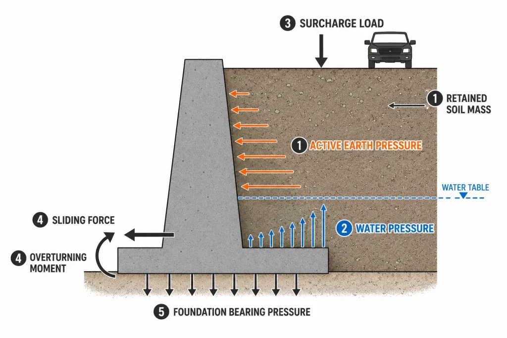
A retaining wall resists lateral earth pressure, the horizontal force that the retained soil exerts on the back face of the wall. This pressure is not uniform: it increases with depth below the top of the wall, with the height of the retained soil, with the density and water content of the retained material, and with surcharge loads, vehicles, structures, or stockpiled material, placed on the retained soil behind the wall.
The wall must resist this lateral pressure without sliding forward, without overturning, and without failing structurally in bending or shear. It must also be able to drain the water that accumulates in the retained soil, undrained water pressure behind a retaining wall can double or triple the total lateral force the wall must resist, and is the most common single cause of retaining wall failure.
These three requirements, adequate sliding resistance, adequate overturning resistance, and adequate drainage, govern every aspect of retaining wall design and construction. Every construction detail described in this guide exists to satisfy one or more of these requirements.
Also read : Types of Bridges: Structures, Uses, and How They Work
Types of Retaining Walls
The most common retaining wall types encountered in construction and civil engineering each use a different structural mechanism to resist lateral earth pressure:
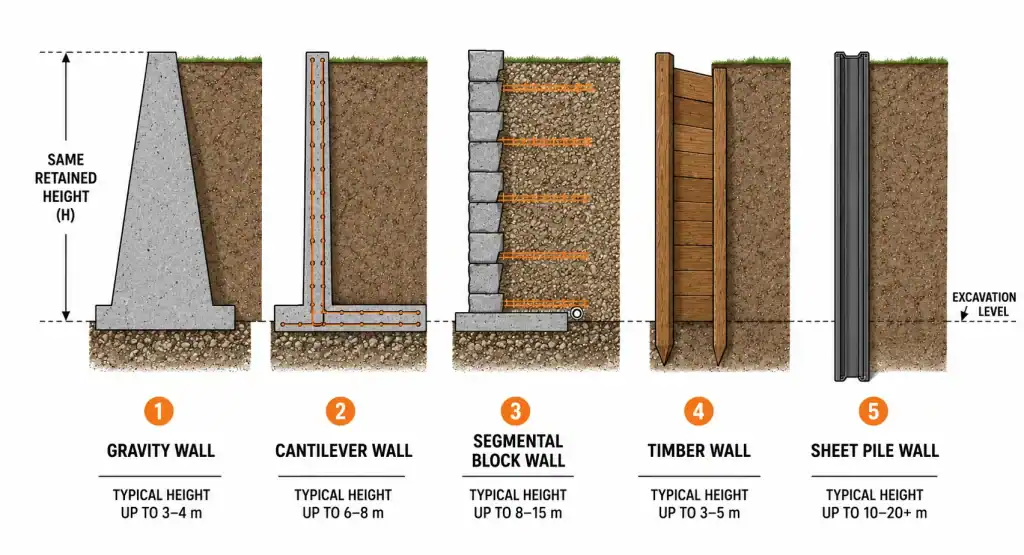
- Gravity retaining wall
Resists earth pressure through its own weight, typically a mass of concrete, masonry, or stone that is heavy enough to resist sliding and overturning without any internal reinforcement. Suitable for walls up to approximately 1.5 metres in height in most ground conditions.
- Cantilever retaining wall
Uses a reinforced concrete base slab that extends beneath the retained soil, with a reinforced vertical stem. The weight of soil on the base slab provides the gravity component, and the reinforcement resists the bending moment in the stem. Economical for wall heights between 1.5 and 6 metres.
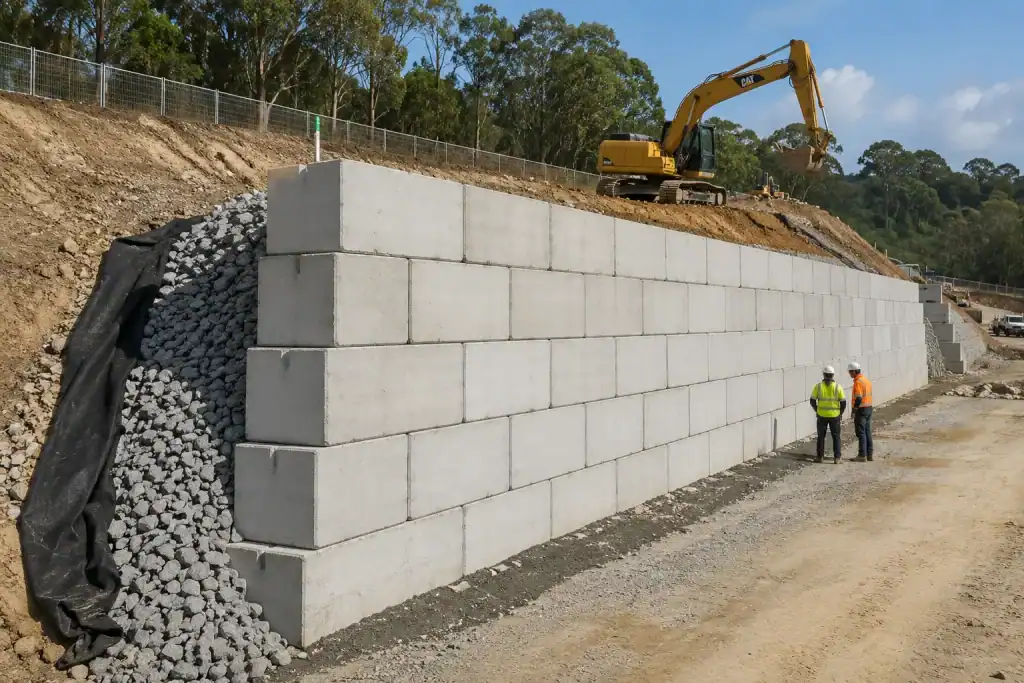
- Segmental retaining wall
Uses dry-stacked or mortared precast concrete blocks, natural stone, or proprietary interlocking units. Can be built by non-specialist labour for low-to-medium heights. For heights above approximately 1.2 metres, geogrid reinforcement layers incorporated into the retained fill are typically required.
- Timber retaining wall
Uses horizontal timber members, sleepers, treated timber planks, supported by vertical timber posts driven or concreted into the ground. Economical and practical for walls up to approximately 1.0 to 1.2 metres, but limited by the service life of the timber in contact with soil.
- Sheet pile retaining wall
Uses interlocking steel, concrete, or vinyl sheet piles driven into the ground. The pile’s embedment depth below the excavation level provides the passive resistance that balances the active pressure on the retained side. Used for temporary excavation support and for permanent walls in limited-space urban environments.
Before Construction Begins: Planning and Design
Site Assessment
Every retaining wall project begins with a thorough site assessment. The assessment must establish:
- The height of retained soil and the extent of the wall
These dimensions directly determine the earth pressure the wall must resist and, therefore, the structural requirements for the wall type, foundation, and drainage.
- The soil type and condition
The density, friction angle, and cohesion of the retained soil determine the magnitude of the lateral earth pressure. Loose fill, saturated clay, and granular material all produce different pressures. The bearing capacity of the foundation soil determines what type of foundation the wall requires.
- The groundwater level
The depth to the groundwater table affects both the earth pressure calculation, saturated soil exerts higher pressure, and the drainage strategy required to prevent water accumulation behind the wall. Sites with high groundwater require more robust drainage provisions.
- The presence of surcharge loads
Vehicles, buildings, or stacked materials behind the wall increase the lateral pressure it must resist. The surcharge loads must be identified and their effect included in the wall design.
- Underground services and existing structures
Before any excavation begins, the location of buried services, gas pipes, electricity cables, water mains, telecommunications cables, must be established from records and confirmed by a cable avoidance tool (CAT) survey. The presence of existing foundations, piles, or drainage structures that might be affected by the wall construction must also be identified.
Design Requirements
For retaining walls above approximately 1.0 metre in height, a structural design by a qualified civil or structural engineer is strongly recommended and in many jurisdictions is legally required. The design must confirm the wall type and dimensions, the foundation requirements, the drainage specification, the reinforcement, and the stability factors of safety. Retaining wall design follows geotechnical design standards published by standards bodies, the British Standards Institution (BSI) and equivalent national standards organisations publish the geotechnical design codes that govern earth pressure calculation, bearing capacity assessment, and stability verification in civil engineering practice.
For walls above approximately 1.5 metres, or walls in proximity to existing structures, roads, or services, the design should be submitted to the relevant local authority for approval before construction begins. Building without consent for a retaining wall that requires it exposes the owner to enforcement action and liability for any consequential damage from wall failure.
How to Build a Retaining Wall: The Construction Sequence
The following construction sequence applies to the most commonly built retaining wall types, gravity masonry and concrete walls, segmental block walls, and reinforced concrete cantilever walls. The specific construction details vary between wall types, but the sequence, foundation preparation, drainage installation, wall construction, backfill, is consistent across types.
Excavate the Foundation Trench
Mark out the wall alignment and excavate the foundation trench to the depth specified in the design. For gravity and segmental walls, the foundation depth is typically 100 to 200 millimetres below the finished ground level on the low side of the wall, enough to provide frost protection and to prevent the base course from being undermined by surface erosion. For cantilever walls, the foundation depth is determined by the structural design, typically 0.4 to 0.6 times the retained height for the base slab embedment.
On sites with soft or variable foundation soil, the foundation trench must be inspected by a competent person before proceeding, if the soil at foundation level does not match the bearing capacity assumed in the design, the design must be revised before construction continues. Placing a wall foundation on soil of lower bearing capacity than assumed in the design is a direct cause of settlement, tilt, and eventual wall failure.
Where excavation is required to form the retained face, cutting back an existing slope or excavating against an existing soil face, the excavation must be carried out safely, with appropriate battering of the cut face or temporary support to prevent collapse. For retaining wall construction involving significant excavation adjacent to existing structures, the selection of the appropriate excavation equipment, including excavator type and size for the confined geometry of a retaining wall trench, directly affects site productivity and the accuracy of the finished excavation. The range of excavator types suited to confined and restricted excavation conditions is covered in the complete guide to types of excavators and their application on construction sites.
Prepare the Foundation
Compact the foundation trench bottom to achieve the bearing capacity required by the design. On weak or disturbed ground, a layer of compacted granular fill, clean crushed rock or gravel, may be required to improve the bearing capacity before placing the wall foundation.
For concrete and masonry walls, place the concrete footing or blinding layer to the dimensions specified in the design. The concrete must be placed and levelled carefully, the top of the footing is the reference level for the first course of masonry or the first lift of concrete, and any error in level at this stage is amplified through every subsequent course.
For segmental block walls, the base course of blocks is placed directly on a compacted granular base, typically 100 to 150 millimetres of compacted crushed rock, without mortar. The base course must be level and must be set back from the face of the excavation to allow for the wall’s drainage layer and filter fabric installation.
Also read : Types of Graders: How Each Works and When to Use One
Install the Drainage System
The drainage system is the most critical element of retaining wall construction and the most frequently omitted or inadequately installed. It must be installed before or concurrent with the lower courses of wall construction, not added as an afterthought after the wall is built.
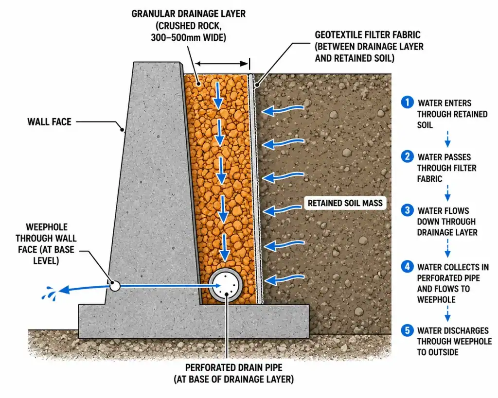
- Drainage layer
A free-draining granular material, clean single-size crushed rock, typically 10 to 20 millimetres in size, placed against the back face of the wall for its full height. The drainage layer must extend at least 300 to 500 millimetres from the wall face. Its purpose is to intercept water flowing through the retained soil and convey it downward to the perforated drain pipe at the base.
- Filter fabric (geotextile)
A permeable geotextile fabric placed between the drainage layer and the retained soil. The filter fabric allows water to pass through while preventing fine particles from migrating from the retained soil into the drainage layer and blocking it. Without the filter fabric, the drainage layer becomes progressively clogged over time and loses its drainage function. Geotextile filter fabric selection, pore size, permeability, and installation requirements, is governed by geotechnical design guidance published by bodies including the Construction Industry Research and Information Association (CIRIA), whose publications on drainage and retaining wall construction are widely referenced in civil engineering practice.
- Perforated drain pipe
A perforated drainage pipe, typically 100 millimetres diameter PVC or HDPE, placed at the base of the drainage layer along the full length of the wall. The pipe collects water flowing down through the drainage layer and conveys it to a discharge point at the end of the wall or through the wall at regular intervals via weepholes.
- Weepholes
Openings through the wall face at regular intervals, typically every 1.5 to 2.0 metres, that allow water from the drainage layer to discharge through the wall face. Weepholes must not be blocked or sealed, they are a critical drainage outlet for the retained soil.
Build the Wall
With the foundation in place and the drainage provisions started, construction of the wall itself proceeds course by course from the bottom upward.
- Masonry and concrete block walls
Each course of block or masonry unit is placed on the course below, with staggered vertical joints between courses for structural continuity. The face batter, the slight backward lean of the wall face toward the retained soil, is maintained throughout construction. A batter of 20 to 50 millimetres per metre of wall height is typical for gravity walls, improving overturning resistance by shifting the wall’s centre of gravity toward the retained side.
- Segmental block walls
Proprietary segmental retaining wall systems are installed per the manufacturer’s technical manual, which specifies the block placement, the setback between courses, the geogrid reinforcement layers and their horizontal extent into the retained fill, and the drainage requirements. Geogrid reinforcement layers, horizontal sheets of polymer mesh embedded in the retained fill at specified intervals, are mandatory for segmental walls above approximately 1.0 to 1.5 metres. The geogrid transfers lateral earth pressure from the retained soil into friction on the geogrid surface, reducing the load on the wall face.
- Reinforced concrete cantilever walls
The base slab is cast first, with the vertical stem reinforcement projecting upward. The stem is then formed and cast in lifts, typically 1.0 to 1.5 metres per lift. The construction joints between lifts must be clean and prepared with a bonding agent before the next lift is placed. The concrete mix, cover to reinforcement, and curing procedure must comply with the structural specification.
Place and Compact the Backfill
Backfilling is carried out in layers, typically 200 to 300 millimetres of compacted fill per layer, with each layer compacted to the specified density before the next is placed. The compaction equipment and methodology must be appropriate to the wall type:
- Keep heavy compaction equipment away from the wall face
The lateral pressure generated by a heavy compactor, a vibrating roller or plate compactor, operating immediately behind the wall face can significantly exceed the design earth pressure and damage or overturn the wall before it has developed its full resistance through the weight of overlying backfill. Compaction within 1.0 metre of the wall face should be carried out with lightweight hand-operated compactors only.
- Use granular, free-draining backfill where possible
Granular material compacts to a stable density more reliably than cohesive clay, produces lower lateral earth pressure than clay at the same density, drains freely without generating water pressure, and is less susceptible to volume change with moisture content variation. Clay backfill, particularly expansive clay, against a retaining wall is a source of ongoing lateral pressure that the wall design may not have accounted for.
The backfilling and compaction phase is where the drainage layer, filter fabric, and drain pipe installation continues as the fill rises, each element must remain correctly positioned and undamaged throughout the backfilling operation.
Finish, Inspect, and Drainage Test
Once the wall is complete to its full height and the backfill is placed and compacted, the following completion tasks are required:
Confirm that all drainage provisions are in place, drainage layer, filter fabric, perforated pipe, and weepholes, and that no element has been dislodged or blocked during construction.
Carry out a drainage test, introduce water behind the wall and confirm that it discharges freely through the weepholes or the drain pipe outlet. A wall whose drainage cannot be confirmed operational before it goes into service has an unknown drainage capacity, the most common precursor to drainage-related wall failure.
Inspect the wall face for cracking, misalignment, or evidence of differential settlement in the foundation. Any deficiency identified at this stage must be investigated and rectified before the wall is accepted.
Record the as-built dimensions, the drainage specification installed, and the inspection results in a completion record. The completion record becomes the baseline for future inspection and maintenance of the wall.
Retaining Wall Construction and Heavy Plant
Retaining wall construction on significant civil and infrastructure projects involves the coordination of multiple plant types, excavators for foundation trenching and slope cutting, compactors for backfill compaction, cranes or lifting equipment for placing precast wall elements, concrete pumps for cantilever wall stem concrete.
On large wall projects, the sequencing of excavation, drainage installation, wall construction, and backfill compaction in a continuous production cycle requires careful plant coordination to avoid conflicts between machine operations and to maintain safe separation between excavation plant and workers placing drainage and wall elements. The principles of coordinating multiple plant types on an active construction site, managing routes, exclusion zones, and task sequencing, are covered in the guide to construction site planning and heavy plant coordination on civil projects.
For walls in proximity to existing structures or where the excavation must proceed close to existing foundations, the ground conditions and the effect of the excavation on adjacent structure foundations must be assessed. An understanding of foundation types and their behaviour under adjacent excavation, including the pile foundation types used in building construction, is relevant context for retaining wall construction on constrained urban sites, as covered in the guide to types of pile foundation and how they interact with adjacent construction.
The earthmoving plant used for excavation and backfill compaction on retaining wall projects, including the selection between different excavator and compactor types based on the geometry of the work and the material conditions, is part of the wider earthmoving equipment knowledge base. For projects where the retaining wall excavation must be carried out in confined spaces or with limited access, understanding the capabilities of compact and standard excavator configurations is directly relevant. The full range of excavator types and their access and production capabilities is set out in the complete guide to types of excavators and their application on construction projects.
Also read : Heavy Equipment Safety: A Complete Site Guide
Build It Right, and It Will Stand
A retaining wall that is correctly designed, correctly drained, and correctly constructed will perform its function for the full design life of the project, typically 50 to 100 years for permanent civil infrastructure, with no more than periodic inspection and minor maintenance. A wall that is under-designed, poorly drained, or built without regard to the forces it must resist will fail, often without warning, and the consequences, slope failure, damage to adjacent structures, road closures, and personal injury, are entirely preventable.
The investment in correct site assessment, competent design, appropriate materials, and disciplined construction sequence is not overhead. It is the minimum requirement for a structure that will be loaded by earth pressure every day of its service life.
RR Machinery provides a comprehensive range of construction and earthmoving equipment for sale and rental, including excavators, compactors, motor graders, and supporting plant for every phase of civil construction, all maintained to full operational standard and supported by experienced equipment specialists. Explore our full range of construction and earthmoving equipment solutions, or contact our team for practical advice and a clear quotation matched to your project scope and site conditions.