
What a Crane Load Chart Is, and What It Is Not
Before working through the mechanics of reading a load chart, it is important to establish what the chart represents. A load chart specifies the maximum rated capacity, the maximum load the crane manufacturer states the crane can lift safely, at defined operating conditions. It is based on structural analysis of the crane’s components and stability analysis of the complete machine. The rated capacities shown include a built-in safety factor, but that safety factor is consumed by the rated capacity itself, not by operating within it. There is no additional margin available for exceeding the rated capacity. What the load chart does not tell you:-
- Whether the ground conditions can support the crane and load, this requires a separate ground bearing capacity assessment
- Whether the lift path is clear of obstructions and hazards, this requires a pre-lift site survey
- Whether the rigging is adequate for the load, this requires a separate rigging assessment
- Whether the load weight has been accurately determined, this is the operator’s and appointed person’s responsibility
Also read : Lifting Equipment Safety: A Practical Guide
The Structure of a Crane Load Chart
 Most crane load charts follow a consistent structure, though the exact format varies between manufacturers. The main components are:
-
-
The rating table
-
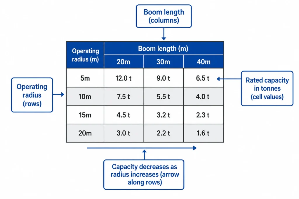
The rating table is the core of the load chart, a matrix of numbers showing the maximum rated load (in tonnes or kilograms) for combinations of operating radius and boom configuration. The rows typically represent operating radius (the horizontal distance from the centreline of the crane’s rotation to the centre of the suspended load). The columns typically represent boom length or boom angle.
The intersection of a given row and column gives the rated capacity for that specific combination of radius and boom configuration. This is the maximum load the crane can lift at that radius and configuration, not a target, not an average, and not a figure to be approached without margin.
-
-
Operating radius
-
Operating radius, sometimes called working radius or load radius, is the horizontal distance, measured from the centreline of the crane’s slewing bearing, to the centre of gravity of the suspended load. It is not the length of the boom, it is the horizontal projection of the boom’s reach.
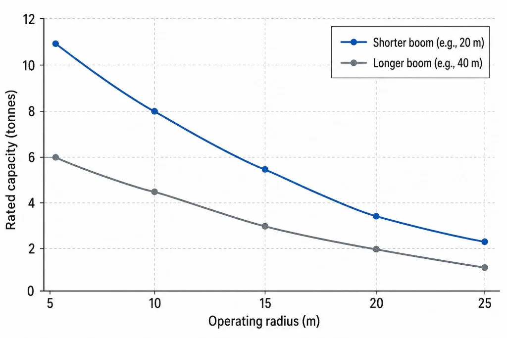
As the operating radius increases, the rated capacity decreases. This is the fundamental relationship that the load chart encodes: a crane that can lift 10 tonnes at 5 metres radius may only be able to lift 3 tonnes at 15 metres radius, using the same boom configuration. The rate of decrease varies with crane design, counterweight, and configuration.
A common error is to measure radius from the centre of the crane’s undercarriage rather than from the centreline of the slewing bearing. On some cranes, particularly large mobile cranes, the slewing bearing centreline and the geometric centre of the undercarriage are in the same position. On others, particularly cranes with offset turntables, they may differ. Always confirm the reference point for radius measurement from the crane’s documentation.
-
-
Boom length and boom angle
-
Many load charts are structured around boom length rather than boom angle, because boom length is a fixed configuration that the operator can read directly from the boom assembly. For a given boom length, the operating radius varies with the boom angle, a steeper angle produces a shorter radius and a higher permitted load; a shallower angle produces a longer radius and a lower permitted load.
Some charts present capacity as a function of both boom length and boom angle, requiring the operator to first determine both values and then find the corresponding capacity in the table. Others present capacity as a function of boom length and operating radius, with the implied boom angle derived from the geometry.
When a jib or fly extension is attached to the main boom, a separate section of the load chart applies, jib configurations typically have significantly lower rated capacities than the main boom alone, and the jib chart must be used rather than the main boom chart.
-
-
Counterweight configuration
-
Most mobile cranes can be configured with different counterweight arrangements, different quantities of counterweight plates stacked on the rear of the machine. Greater counterweight increases the rearward restoring moment, allowing heavier loads to be lifted at greater radii without the machine tipping forward.
The load chart includes separate capacity tables for each permitted counterweight configuration. Using a capacity figure from a table that corresponds to a counterweight configuration different from the one actually installed on the crane is a serious error that will invalidate the chart’s safety assurance.
Before reading the load chart, confirm the exact counterweight configuration installed on the crane and use only the corresponding section of the chart.
-
-
360-degree vs restricted slewing
-
Mobile cranes, particularly those configured with outriggers extended, may have different rated capacities in different slewing zones. Over the rear of the crane, where the counterweight provides maximum stabilising effect, capacities are highest. Over the side, capacities are typically lower. Over the front, capacities may be lower still, or the crane may be prohibited from lifting over the front entirely.
The load chart indicates whether the capacities shown apply over the full 360-degree slewing range or are restricted to specific sectors. When the lift requires the crane to slew over a restricted zone, the capacity for that zone must be used.
For cranes operating on outriggers, full outrigger extension is typically required to achieve the rated capacities shown in the main chart. Partial outrigger extension, used when ground conditions or space constraints prevent full extension, reduces the available capacity. A separate section of the load chart, or a separate chart entirely, will specify the reduced capacities for partial outrigger configurations.
Step-by-Step: How to Look Up the Rated Capacity for a Specific Lift
Working through the following sequence ensures that the correct rated capacity is identified for any specific lift:-
-
Confirm the crane configuration
-
Before referencing the load chart, confirm:
-
-
- Counterweight configuration (number and arrangement of counterweight plates)
- Outrigger configuration (full extension, partial extension, or on tyres)
- Boom length and any jib or fly extension attached
- The slewing zone over which the lift will occur
-
Select the section of the load chart that corresponds to this exact configuration.
-
-
Determine the operating radius
-
Measure or calculate the operating radius for the lift, the horizontal distance from the centreline of the slewing bearing to the centre of gravity of the load at its pick-up position, and at its set-down position. Use the greater of the two radii when looking up the rated capacity.
If the load must travel through a larger radius during the lift, for example, if the load swings outward as it is raised due to boom deflection, this maximum radius during travel must be used, not merely the initial or final radius.
-
-
Read the rated capacity from the table
-
Locate the row corresponding to the operating radius and the column corresponding to the boom length (or boom angle, depending on the chart format). The number at their intersection is the rated capacity in the units shown, confirm whether the chart is in tonnes, kilograms, or another unit.
If the exact radius or boom length falls between two values in the table, interpolation is not generally permitted unless specifically allowed by the crane manufacturer. Use the more conservative (lower capacity) adjacent value.
-
-
Apply derating factors
-
The rated capacity from the table must be reduced to account for the following factors:
-
-
- Rigging weight
-
The weight of all rigging equipment, slings, shackles, hooks, lifting beams, must be deducted from the rated capacity to determine the maximum net load that can be lifted. Rigging that is visually light can weigh significantly more than operators estimate. Weigh all rigging hardware or use certified weight data from the manufacturer.
-
-
- Hook block weight
-
The hook block, the pulley assembly and hook that is attached to the hoist rope, has a significant weight that must be included in the total lift weight. The hook block weight is typically shown on the load chart as a deduction.
-
-
- Dynamic loads
-
During crane operations, hoisting, slewing, luffing, dynamic forces develop that increase the effective load on the crane structure. Most load charts are based on static conditions. Where dynamic lifting is involved (rapid hoisting, lifting in wind, lifting from water), additional derating may be required.
-
-
- Wind
-
Wind loading on a large or flat load can significantly increase the effective load on the crane. Where wind speeds exceed the manufacturer’s specified limit for crane operation, the lift must be suspended.
Also read : Parts of a Crane: Key Components and How They Work
-
-
Compare the derated capacity to the actual load
-
The derated rated capacity, after all deductions, must exceed the actual load weight. If the actual load weight is unknown or uncertain, a conservative upper-bound estimate must be used. If the load weight exceeds the derated capacity at any radius during the lift, the lift must not proceed.
Common Load Chart Reading Errors
 Even experienced operators make systematic errors when reading load charts. Understanding these errors reduces the risk of misapplication:
-
- Using the headline capacity
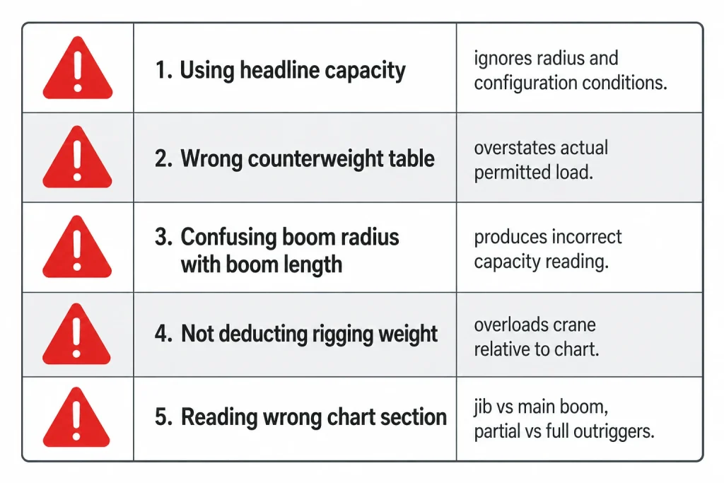
The figure prominently displayed on the crane body or in marketing material is the maximum capacity under optimal conditions, typically at minimum radius with maximum counterweight and full outrigger extension. This figure is almost never achievable in actual site conditions where the lift radius is greater than the minimum.
-
- Ignoring the counterweight configuration
A crane on site may have less counterweight installed than the maximum permitted, either because the full counterweight was not transported or because ground conditions restrict the load. Using the maximum-counterweight capacity tables when less counterweight is installed significantly overstates the actual permitted capacity.
-
- Confusing boom radius with boom length
These are different values. Boom length is the physical length of the boom from pin to pin. Boom radius is the horizontal distance from the slewing centreline to the load. At a given boom length, the radius varies with the boom angle. Substituting one for the other produces incorrect capacity readings.
-
- Not accounting for rigging weight
On heavy lifts, the combined weight of a multi-leg sling arrangement with a large hook block can add one to three tonnes to the total lift weight. Ignoring this overloads the crane relative to the chart value.
-
- Reading the wrong section of the chart
A crane configured with partial outrigger extension is a different machine from the same crane on full outriggers. Using the full-outrigger chart for a partial-outrigger configuration is a serious error. The same applies to using the main boom chart when a jib is fitted.
These errors compound, a lift that uses the wrong counterweight table, ignores rigging weight, and reads radius as boom length can produce a calculated permitted load that is twice the actual safe limit for the operation as configured. This is how serious overloads occur without any deliberate intent to exceed the rated capacity. Understanding the components that make up a crane system, and how each one affects lifting performance, is covered in detail in practical guides to crane components and their functions.Load Charts for Tower Cranes and Overhead Cranes
While this guide has focused primarily on mobile crane load charts, the same principles apply to other crane types with some differences in chart format.Tower crane load charts
Tower crane load charts typically present rated capacity as a function of radius from the mast centreline. Unlike mobile cranes, tower cranes do not have variable counterweight or outrigger configurations in normal operation, the chart is therefore simpler in structure. The rated capacity typically applies over the full 360-degree slewing range.
Tower crane charts often show a “maximum load” line and a “maximum radius” line, the crane must operate within both limits simultaneously. Some tower cranes have a horizontal jib with a trolley that travels along the jib; the chart shows the rated capacity at each trolley position (radius).
Overhead crane load charts
Overhead cranes typically have a single rated capacity rather than a variable chart, because the crane operates along fixed rails and the operating radius does not vary in the same way as a boom crane. However, the rated capacity may vary depending on whether the crane is operating with one or two hoists, and whether the trolley is at mid-span or over a support.
Understanding these distinctions is directly relevant to selecting the right type of crane for specific lifting tasks, a decision that requires understanding both the load chart implications and the operational differences between crane types before any crane is specified for a project. For technical reference on crane load rating standards, structural analysis methodology, and international standards for crane capacity testing and certification, engineering resources on crane design and load rating standards provide useful background on how the values in a load chart are calculated and verified.Also read : Types of Excavator Buckets and Their Uses Explained
Read the Load Chart. Every Lift. Every Time.
A crane load chart is not a reference document to consult once during project setup and then file away. It must be consulted before every lift in which the operating conditions change, different radius, different configuration, different counterweight, different operating zone. The few minutes required to correctly read the chart are the most valuable minutes in any lifting operation. The margin between a safe lift and a catastrophic overload is often smaller than operators assume. Cranes do not give a warning before they tip, they are stable, and then they are not. Reading the load chart correctly, every time, is the primary engineering control that keeps the operation on the safe side of that margin. RR Machinery provides a comprehensive range of lifting and access equipment for sale and rental, including forklifts, boom lifts, scissor lifts, mobile scaffolding, and power generators, all maintained to operational standard and supported by experienced technicians who understand the demands of construction and industrial lifting operations. Explore our full range of construction equipment solutions or contact our team for practical advice and a clear quotation tailored to your project requirements.


Very clear explanation of crane load charts. It highlights why misreading radius and boom angle can directly lead to unsafe lifting operations.