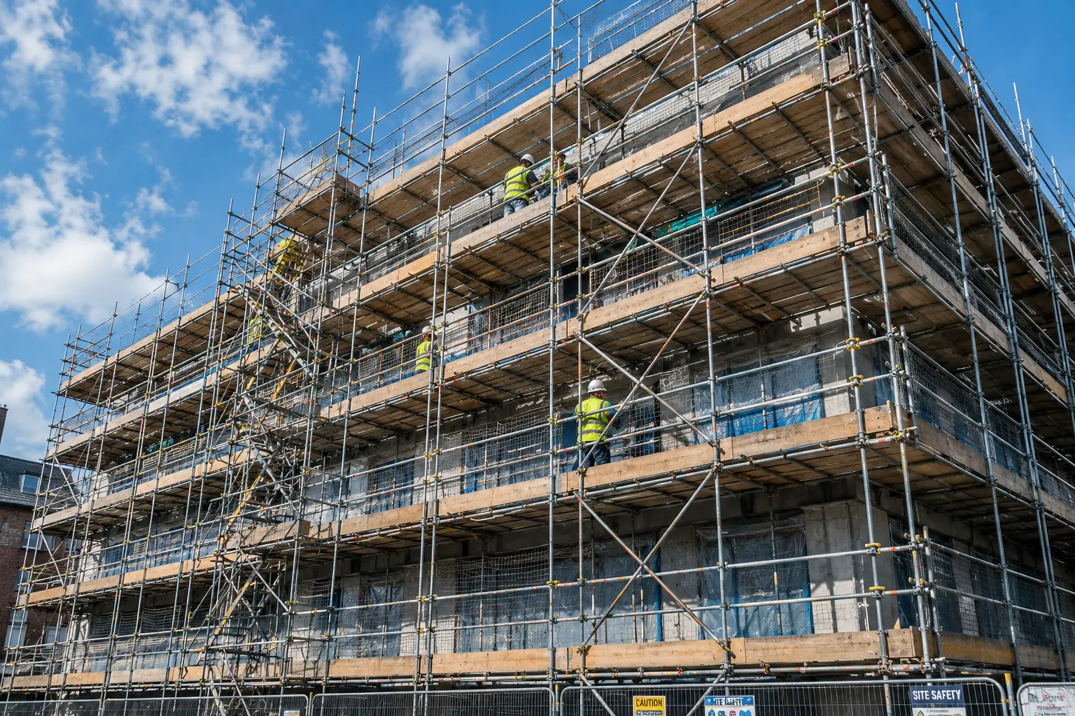
What Is Scaffolding and When Is It Required?
Scaffolding is a temporary structure, typically of steel tube and fittings, or of prefabricated system components, erected to provide a working platform, access, or support at height. It is distinct from other working-at-height solutions such as mobile elevated work platforms (MEWPs), boom lifts, and scissor lifts in that it provides a fixed platform that remains in position throughout a phase of work, rather than being repositioned for each individual task. Scaffolding is the right choice when work at height is repetitive, when multiple trades need simultaneous access to the same elevation, when the work area is too large for a single mobile platform to cover efficiently, or when the duration of the work makes a fixed access structure more economical than continuous MEWP deployment. Typical applications include building facade renovation, brickwork and render at height, roofing access, structural repair, painting and surface treatment of large structures, and the construction of new buildings where every floor level requires access for multiple trades. For shorter-duration tasks, single-trade access, or locations where scaffolding erection would create unacceptable disruption to the site or the surrounding environment, mobile scaffolding towers, boom lifts, or cherry pickers may be more appropriate. Understanding which working-at-height solution is right for any given task requires a clear comparison of the access geometry, the duration, the number of users, and the site conditions, considerations covered in the context of boom lifts, cherry pickers, and when each type of aerial work platform is the right choice.Also read : What Is a Cherry Picker? Types, Uses and How It Works
Before Erection Begins: Planning and Design
Scaffold Design and Loading Assessment
Every scaffold must be designed before it is built. For standard configurations covered by published standards and manufacturer guidance, the design may take the form of a method statement and loading calculation prepared by a competent scaffolder. For complex, non-standard, or heavily loaded scaffolds, including those supporting formwork, carrying significant material storage loads, or exceeding standard height-to-base ratios, a scaffold design by a qualified structural engineer is required. The design must establish the scaffold’s duty class, the load per bay per platform level that the scaffold is rated to carry. Scaffold duty classes range from light-duty inspection platforms to heavy-duty configurations carrying masonry materials, formwork, or mechanical plant. Using a light-duty scaffold for heavy-duty work is one of the most consistent causes of scaffold overload failures. The design must also address the method of tying the scaffold to the building or structure it serves. Scaffold ties, connections between the scaffold and the building facade, are critical to stability under wind load and eccentric loading. The number, type, and spacing of ties must be determined by the design, and the design must account for the tie locations available on the specific building facade.Ground and Foundation Assessment
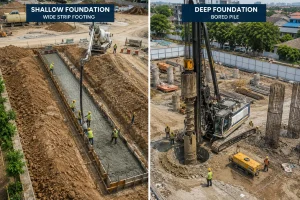
The ground beneath the scaffold standards, the vertical tubes that carry the scaffold’s load to the ground, must be capable of sustaining the loads transmitted through the base plates. On soft, disturbed, or made ground, the point loads from scaffold base plates can cause differential settlement, which tilts the scaffold and compromises its structural integrity. Before erection begins, the ground must be assessed for bearing capacity. On sites where ground conditions are poor, recently disturbed soil, made ground, or ground softened by rainfall, sole boards must be placed beneath the base plates to distribute the load over a larger ground area. The length, width, and thickness of the sole boards must be appropriate to the ground conditions and the load being distributed. This assessment is directly analogous to the ground-bearing assessment required before any mobile lifting equipment is deployed, the same principles of load distribution, bearing capacity, and settlement risk apply to scaffolding base loads as to crane outrigger and lifting equipment ground assessment.Site-Specific Risk Assessment and Method Statement
A site-specific risk assessment and method statement (RAMS) must be prepared before erection begins. The RAMS must identify the hazards associated with the erection process itself, working at progressively increasing heights during erection before full handrails and platforms are in place, and the control measures that will be applied at each stage. The method statement must describe the erection sequence, the tie installation sequence, the platform boarding sequence, and the arrangements for preventing falls and falling objects during erection. It must also identify the competency requirements for the erection team and the inspection and handover process that will be followed before the scaffold is handed over for use.Also read : Rough Terrain Crane: How It Works and When to Use It
Components of a Standard Scaffold
 Before describing the erection sequence, it is necessary to understand the principal components of a tube-and-fitting scaffold and the function of each:
-
- Standards
The vertical tubes that carry the scaffold’s load to the ground. Standards are placed at regular intervals along the scaffold’s length and must be plumb, vertical, within the tolerances specified in the relevant standard.
-
- Ledgers
Horizontal tubes running along the length of the scaffold, connecting the standards at each lift height. Ledgers provide the primary horizontal bracing to the scaffold and carry the transoms.
-
- Transoms
Horizontal tubes running across the width of the scaffold, connecting the inner and outer standards at each lift. Transoms support the scaffold boards that form the working platform.
-
- Scaffold boards
Timber or metal boards laid across the transoms to form the working platform surface. Boards must be of the correct grade, must overhang the transoms by the correct amount, and must be secured against displacement and uplift.
-
- Couplers
The fittings that connect tubes at right angles (right-angle couplers), at other angles (swivel couplers), or end-to-end (sleeve couplers and joint pins). The correct type of coupler must be used for each connection, using a swivel coupler where a right-angle coupler is required reduces the connection’s load capacity.
-
- Base plates
Steel plates fitted to the base of each standard, distributing the standard’s point load over a larger area and providing a level bearing surface.
-
- Sole boards
Timber boards placed beneath the base plates on soft or uneven ground to distribute the load further.
-
- Scaffold ties
Connections between the scaffold and the building facade, providing lateral restraint against wind loads and preventing the scaffold from falling away from or into the building.
-
- Bracing
Diagonal tubes fitted to the scaffold to provide longitudinal and facade bracing, preventing the scaffold from racking under horizontal load.
-
- Handrails and toe boards
The fall prevention components fitted to every working platform, a main handrail at approximately 950 mm height, an intermediate rail at approximately 470 mm, and a toe board at platform level to prevent tools and materials from being kicked off the edge.
How to Build Scaffolding: The Erection Sequence

-
-
Prepare the Ground and Position Sole Boards and Base Plates
-
Begin at ground level. Clear the area beneath the scaffold footprint of debris, loose material, and any obstruction that would prevent sole boards from sitting flat. On soft or disturbed ground, lay sole boards perpendicular to the line of the scaffold, spanning across the ground beneath each pair of standards, to distribute the base plate loads.
Position base plates on the sole boards at the correct spacing for the scaffold design. Standard bay lengths for tube-and-fitting scaffolding are typically between 1.8 and 2.4 metres; the specific bay length must match the design. Ensure base plates are level, use packing beneath sole boards where the ground gradient requires it, but never use packing within the standard itself above the base plate.
-
-
Erect the First Lift Standards and Ledgers
-
Insert the first lift standards into the base plates at each base plate position along the scaffold run. Standards for tube-and-fitting scaffold are typically 48.3 mm outside diameter steel tube. Use a spirit level or plumb bob to check each standard for plumb as it is positioned, correcting plumb errors at the first lift is far easier than at subsequent lifts.
Once the first pair of standards is in position, fit the first ledger, the horizontal tube connecting the two standards at the first lift height, typically between 2.0 and 2.2 metres above ground. Use a right-angle coupler to connect the ledger to each standard. Check the ledger for level.
Continue erecting standards and fitting ledgers along the full length of the scaffold run before proceeding to the next step. Completing each full lift before advancing to the next gives the scaffold structure its lateral stability progressively as height is gained.
-
-
Fit Transoms and Bracing at the First Lift
-
With the first lift ledgers in place along the full scaffold length, fit the transoms, the tubes running across the scaffold width, at each standard position and at intermediate positions where boarding requires support. Transoms are connected to the ledgers with right-angle couplers.
Fit longitudinal bracing, diagonal tubes connecting standards at an angle of approximately 45 degrees along the facade, at the intervals specified in the design. Bracing is typically fitted at alternate bays and must be fixed to standards, not to ledgers, using right-angle couplers. Facade bracing, diagonal tubes running across the face of the scaffold in the vertical plane, must also be fitted at the intervals specified in the design.
-
-
Board Out the First Lift Platform
-
Lay scaffold boards across the transoms of the first lift to form the working platform. Boards must span in the correct direction, across the transoms, and must overhang the end transoms by between 50 mm and 150 mm. Boards must not overhang by more than four times their thickness to avoid the risk of the overhanging end being stepped on and the board tipping.
On working platforms, boards must be laid close-boarded, with no gaps greater than 25 mm between adjacent boards, and must be secured against displacement by the wind and against uplift. Board clips or transom-height packing beneath the board ends are used to prevent longitudinal movement.
Fit the handrail and intermediate rail above the platform, and the toe board at the platform edge, before the platform is used or before work proceeds to the lift above. This is a critical sequencing point: the platform below must be fully guarded before the erection team advances to the next lift.
-
-
Install Scaffold Ties
-
Scaffold ties must be installed as erection proceeds, not after the scaffold is fully erected. The tie pattern specified in the design must be followed precisely, with ties installed at the heights and horizontal spacings specified.
Standard tie types include through ties, tubes passed through window or door openings and connected to the scaffold on both sides, and reveal ties, in which a tube is wedged into a window or door reveal under compression and connected to the scaffold. Where neither is available, anchor ties using proprietary resin or mechanical anchors in the facade may be used, but the anchor capacity must be verified before reliance is placed on them.
The scaffold must not be advanced beyond the height at which ties are required without those ties being in place. Erecting scaffold above the first tie point without installing the tie is one of the most dangerous errors in scaffold construction, the scaffold becomes progressively more unstable with every lift erected above an uninstalled tie position.
-
-
Repeat for Subsequent Lifts
-
With the first lift complete, standards extended, ledgers fitted, transoms in place, boarding laid, handrails and toe boards fitted, and ties installed, repeat the sequence for each subsequent lift. Extend standards using sleeve couplers or joint pins at staggered heights, never at the same height in adjacent standards, to avoid creating a plane of weakness across the scaffold.
At each lift, check the plumb of the standards, the level of the ledgers, and the tightness of all couplers before advancing to the next lift. Couplers that are insufficiently tightened, a common site deficiency, significantly reduce the load capacity of the connection and can lead to progressive collapse.
-
-
Complete the Top Lift and Fit All Edge Protection
-
At the final working platform level, complete the boarding and fit the full edge protection, main handrail, intermediate rail, and toe board, on all open sides and ends of the platform. No working platform may be used without complete edge protection in place.
Where the scaffold serves a roof or parapet at or near the top lift level, additional precautions may be required, including scaffold fans or netted barriers, to prevent materials from falling from the upper working area to the ground below.
Scaffold Inspection and Handover
A scaffold must not be used until it has been inspected by a competent person and a scaffold inspection record has been completed and signed. The inspection must cover every element of the completed scaffold, ground conditions and base plates, plumb of standards, level of ledgers, tightness of couplers, completeness of boarding, correctness of handrail heights, installation of all specified ties, adequacy of bracing, and the condition of all boards and fittings. The scaffold inspection record must be retained on site and must be available for inspection by the scaffold users, the principal contractor, and any regulatory authority. In most jurisdictions, scaffolds must be re-inspected at intervals not exceeding seven days, and after any event, severe weather, impact, alteration, that may have affected the scaffold’s integrity. The inspection and handover process is directly parallel to the pre-use inspection and pre-lift planning requirements that apply to all categories of lifting and access equipment. The principles of systematic check, documented record, and competent sign-off are universal across working-at-height operations, as set out in guidance on lifting equipment safety and pre-use inspection requirements.Common Errors in Scaffold Erection
 Understanding the most frequent causes of scaffold failure helps supervisors and inspectors identify deficiencies before they become incidents:
-
- Insufficient or missing ties
Ties omitted to avoid drilling the facade, or not installed at the specified height because the tie point was not available. The scaffold design must be adapted to provide ties at alternative positions, ties must not simply be omitted.
-
- Unsupported standards on soft ground
Base plates placed directly on soft or disturbed soil without sole boards, causing differential settlement and loss of plumb.
-
- Undertightened couplers
Couplers insufficiently tightened during erection, typically because of pressure to advance quickly, reduce connection capacity and allow movement under load.
-
- Boards with excessive gaps or overhang
Gaps between boards large enough to trap a foot, or boards overhanging by more than the permitted maximum, create trip and tip hazards on the working platform.
-
- Edge protection fitted incorrectly
Handrails at incorrect heights, intermediate rails missing, or toe boards not fitted to all open edges, each deficiency reduces the effectiveness of the fall prevention system.
-
- Scaffold overloaded beyond its rated duty class
Materials stacked on the platform beyond the design load, a common occurrence when deliveries are made to the scaffold without reference to the duty class, can cause progressive overloading of the standards and couplers.
The importance of correct scaffold design, erection, and inspection is directly comparable to the precision required in all structural temporary works on construction sites, including the design and assessment of crane positions, temporary support structures, and foundation conditions. For large construction projects where scaffolding and crane operations must be coordinated in the same space, an understanding of construction site planning and the management of lifting zones, exclusion areas, and access routes is essential for avoiding conflicts and maintaining safe site conditions throughout the construction programme.Scaffold Dismantling
Dismantling a scaffold follows the reverse of the erection sequence, working from the top down. The top lift boards, handrails, and edge protection are removed first, then the standards are progressively cut back as each lift is dismantled. Ties must not be removed until the scaffold above the tie level has been fully dismantled, removing ties prematurely during dismantling exposes the remaining scaffold to the same instability risk as failing to install them during erection. All components removed during dismantling must be lowered to ground level using a materials hoist, crane, or gin wheel, never thrown or dropped. A protected dropping zone below the scaffold must be established if components are to be lowered by rope, and access to the zone below must be controlled throughout the dismantling operation.Also read : Types of Pile Foundation: How They Work and How to Choose
Build Right, Work Safely
Scaffolding is a safety-critical structure. Its erection is not a task to be improvised, accelerated beyond safe sequence, or handed to untrained personnel. Every stage, from ground assessment and design through erection sequence and inspection to dismantling, carries specific safety obligations and technical requirements that must be met before the next stage proceeds. Where scaffolding is not the most appropriate working-at-height solution for a specific task, whether because the duration is too short, the access geometry is more suited to a mobile platform, or the site conditions make scaffold erection impractical, RR Machinery offers a comprehensive range of alternatives, including mobile scaffolding towers, articulating and telescopic boom lifts, scissor lifts, and cherry pickers, all maintained to full operational standard. Explore our full range of mobile scaffolding and access tower options, or contact our team for practical advice and a clear quotation tailored to your working-at-height requirements and site conditions.