Bridges are among the most demanding civil engineering structures ever built. They must carry dynamic loads, vehicles, trains, pedestrians, wind, across a span where no intermediate support from the ground below is possible or practical. Every bridge type is an engineering answer to the same fundamental question: how do you transfer load across a gap to the foundations on either side?
The answer has produced a surprisingly varied family of structural forms. Beam bridges, arch bridges, truss bridges, cable-stayed bridges, suspension bridges, and cantilever bridges all solve the load-transfer problem differently, with different structural logic, different material requirements, different span capabilities, and different construction demands. Each type has a category of application for which it is the most economical, the most practical, or the only feasible solution.
For project engineers, construction planners, and infrastructure professionals, understanding the principal bridge types, what each one is, how its structure works, what it is suited to, and what the construction process involves, is foundational knowledge for any project that involves bridge design, procurement, or construction management.
The Structural Logic of Bridge Design
Before examining individual bridge types, it is worth establishing the structural principle that distinguishes them. Every bridge must transfer the loads applied to its deck, traffic, self-weight, wind, thermal expansion, to its foundations. The path that load takes through the structure determines the bridge type.
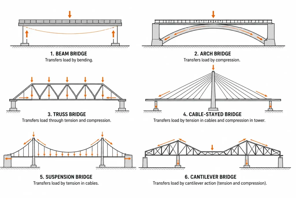
Beam bridges transfer load by bending, the deck acts as a beam spanning between supports, and the bending moment is resisted by the beam’s depth and material strength.
Arch bridges transfer load by compression, the curved arch form converts vertical loads into compressive forces that travel along the arch to the abutments, where they are resolved into the ground.
Truss bridges transfer load through a network of triangulated members, each member carries either pure tension or pure compression, making efficient use of material compared to a solid beam.
Cable-stayed and suspension bridges transfer load through tension in cables, the deck hangs from cables that carry the load back to towers and anchorages.
Cantilever bridges transfer load by extending a beam or truss from its support on one side, balancing the loads on either side of the pier.
Each structural logic has implications for span capability, material use, foundation demands, and construction method, and therefore for the equipment, lifting capacity, and site logistics required to build it.
Also read : Rough Terrain Crane: How It Works and When to Use It
Types of Bridges
The main bridge types in use today each represent a distinct structural solution, suited to a specific range of spans, site conditions, and construction constraints. Understanding what distinguishes each type, in structural terms, in application, and in the construction demands it places on equipment and logistics, is essential for anyone involved in bridge design, procurement, or project delivery.
Beam Bridge
The beam bridge is the simplest and most widely used bridge type in the world. Its structural form is directly analogous to a plank laid across a stream: a horizontal beam, or series of beams, spans between two supports, carrying loads by bending.
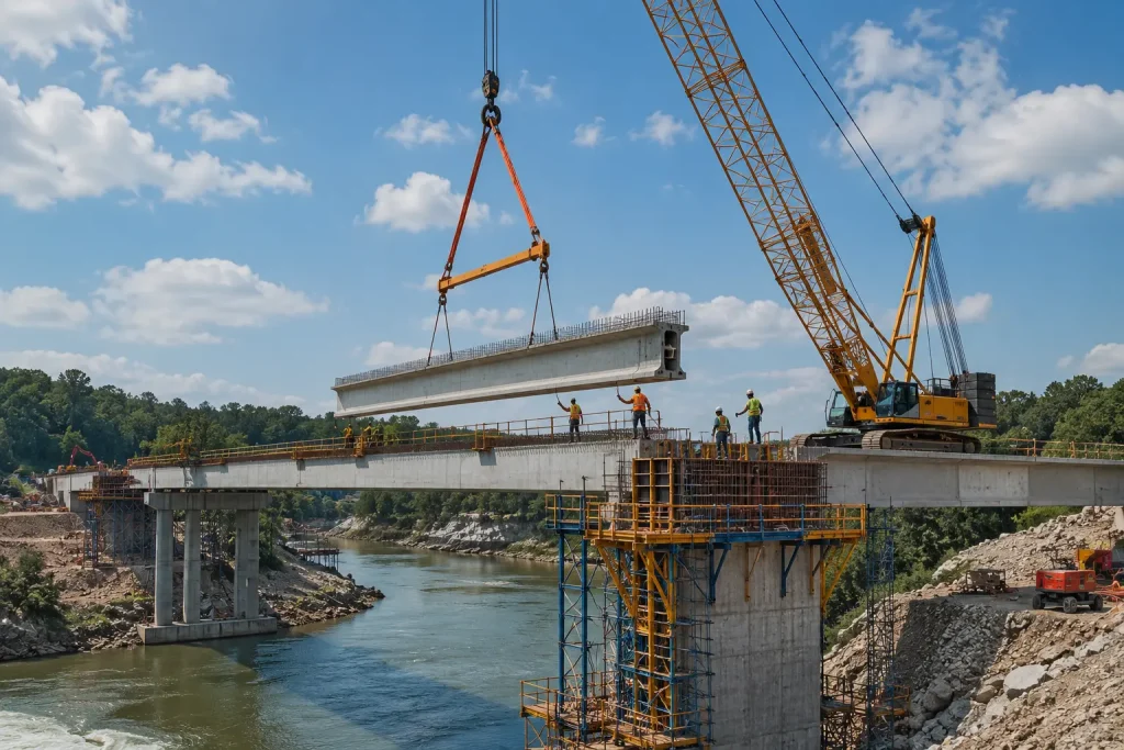
In modern construction, beam bridges use steel I-beams, prestressed concrete beams, or composite steel-concrete deck sections as the primary spanning elements. The beams are manufactured off-site, cast in a precast yard for concrete, fabricated in a steelwork shop for steel, and transported to the bridge site for erection.
Beam bridges are suited to short and medium spans, typically up to approximately 100 metres for a single span, though multi-span beam bridges can cross much greater total distances. They are the default choice for motorway overpasses, railway bridges in flat terrain, pedestrian footbridges, and river crossings where the span is within the range that standard precast or fabricated beams can cover economically.
The construction of a beam bridge typically involves the erection of temporary falsework or the use of launching equipment to position the beams across the span. For concrete beam bridges, a beam launcher, a specialist piece of heavy lifting equipment that straddles the span and lowers precast beams into position from above, is frequently used. For steel beam bridges, mobile cranes or crawler cranes position the fabricated sections.
The relatively straightforward geometry and the availability of standardised precast beam sections make the beam bridge the most economical choice for a wide range of standard infrastructure applications. Where ground conditions and site access allow conventional crane positioning, the construction process is well-understood and efficient. Selecting the right crane type and capacity for beam bridge erection requires a clear understanding of beam weights, lift radii, and the access constraints at each pier location, considerations directly relevant to the guidance on types of cranes and their application to civil engineering lifting tasks.
Arch Bridge
The arch bridge is one of the oldest structural forms in engineering history, with masonry arch bridges in continuous service for over two thousand years. Its durability and structural elegance derive from a single principle: the arch converts vertical loads into compressive forces, and masonry, stone, concrete, and steel are all highly capable of resisting compression.
In a true arch bridge, the deck loads are transferred to the curved arch rib, which carries them as compression to the abutments at each end of the span. The abutments must resist not just the vertical component of the arch thrust but also the horizontal outward thrust, the force that tends to push the arch feet apart. Founding arch bridges requires robust abutments, and the ground conditions at the abutment locations are a critical determinant of whether an arch form is feasible.
Modern arch bridges use reinforced concrete or structural steel for the arch rib, enabling much longer spans than masonry arches could achieve. Steel arch bridges can span several hundred metres, the Sydney Harbour Bridge, at 503 metres, is the most familiar example, and are suited to gorge crossings, river crossings, and locations where the visual impact of the bridge is part of the design brief.
The construction of a modern arch bridge is among the most complex in civil engineering. The arch cannot carry load until it is complete, until the two half-arches meet at the crown, the partially constructed arch is structurally unstable without temporary support. Construction methods include building the arch on temporary falsework, using cable-stayed temporary support from towers during construction, or building each half of the arch as a cantilevered structure that meets at the crown, the latter requiring precise geometry control and temporary tie-back cables.
Arch bridge construction in gorge or water crossing locations often requires crane access on both sides of the span simultaneously, with significant lifting capacity demands during the erection of arch rib segments. For sites with limited ground access, the riverbank conditions typical of arch bridge locations, crawler cranes, barge-mounted cranes, or heavy-duty rough terrain equipment may be required.
Truss Bridge
A truss bridge uses a framework of interconnected triangular units, the truss, as its primary structural element. The triangulated geometry ensures that every member in the truss carries either pure tension or pure compression, with no bending. This makes very efficient use of material: the same load can be carried with significantly less steel than an equivalent solid beam, making truss bridges economical for medium to long spans where beam depth would be excessive.
Truss bridges are most commonly seen in railway bridge applications, where live loads are heavy and dynamic, and where the depth available for the structure is limited, and in highway bridge applications from the mid-twentieth century, particularly in North America. The Warren truss, Pratt truss, and Howe truss are the most common configurations, each differing in the orientation of the diagonal members and therefore in which members carry tension and which carry compression.
The construction of a truss bridge involves the assembly of individual steel members, fabricated in a workshop to precise lengths and connection geometry, into the truss structure on site. This assembly can be carried out on falsework at deck level, by cantilevering the truss out from the piers using a launching technique, or by assembling the truss on the bank and sliding or floating it into position.
Truss bridge maintenance and inspection is a significant operational consideration. The large number of individual members, connections, and gusset plates creates many locations where fatigue cracking, corrosion, and connection deterioration must be monitored. Access to truss members at height and over water requires appropriate working-at-height equipment, the same category of aerial work platform and boom lift used in other inspection and maintenance applications.
Cable-Stayed Bridge
The cable-stayed bridge is the dominant bridge type for medium to long spans in modern infrastructure construction, spanning from approximately 200 metres to over 1,000 metres. Its structural form is immediately recognisable: one or more tall towers rise above the deck, and cables run directly from the tower to multiple points along the deck, supporting the deck in a fan or harp arrangement.
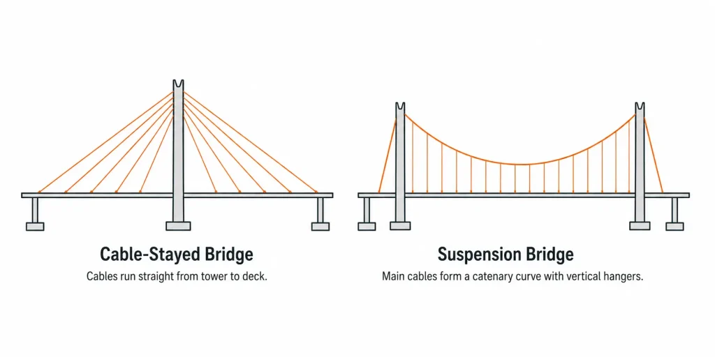
The cables carry the deck load in tension directly to the tower, which transfers the load to its foundations in compression. Unlike the suspension bridge, the cables in a cable-stayed bridge are straight, running directly from tower to deck attachment point, rather than following a catenary curve. This gives the cable-stayed bridge greater deck stiffness and makes it more resistant to the aerodynamic effects that can affect suspension bridges.
Cable-stayed bridges are suited to river crossings, harbour crossings, and any location where a long span is required and where the visual prominence of the structure is acceptable or desirable. They have largely replaced suspension bridges for new construction in the medium-to-long span range because they are faster to build, more economical in cable steel, and more tolerant of asymmetric loading.
The construction of a cable-stayed bridge typically proceeds by balanced cantilever, deck segments are added symmetrically on either side of the tower, each segment supported by the next cable before the following segment is added. This construction method minimises the need for falsework over the span but requires careful sequence management and precision in cable tensioning. Tower construction requires crane access at significant height, typically achieved using climbing tower cranes or derrick cranes mounted on the tower itself as it rises.
Also read : What Is a Cherry Picker? Types, Uses and How It Works
Suspension Bridge
The suspension bridge achieves the longest spans of any bridge type. The main cables, large-diameter wire rope or parallel wire strand bundles, hang in a catenary curve between the towers and are anchored at each end in massive anchorage blocks or directly into rock. Vertical hanger cables connect the main cable to the deck below, suspending the deck along its length.
The structural logic is one of the most elegant in engineering: the entire weight of the deck and its traffic loads is carried in tension in the main cables, transferred to the towers in compression, and resolved into the anchorage or ground at each end. The towers carry only compression, the horizontal component of the cable tension is carried entirely by the cable itself, resolved at the anchorages.
This efficiency in structural logic enables suspension bridges to span distances that no other bridge form can match economically. The Akashi Kaikyō Bridge in Japan spans 1,991 metres in a single main span, a dimension that no beam, arch, truss, or cable-stayed bridge can approach. For crossings of wide straits, deep water channels, or locations where intermediate piers are not feasible, the suspension bridge remains the only viable structural solution.
The construction of a suspension bridge is a specialised process that proceeds in a defined sequence: towers first, then main cables spun or prefabricated and erected in position, then hangers installed, then the deck constructed from the centre outward in balanced segments. The cable spinning process, in which individual wire strands are laid across the span and compacted into the finished cable, is one of the most technically demanding operations in civil construction, requiring specialist equipment and precise quality control at every stage.
Cantilever Bridge
A cantilever bridge extends its structural members outward from the pier on both sides, each arm of the cantilever is anchored by the weight of the back span and the pier foundation, allowing the forward arm to project over the span without immediate support from below. Two cantilever arms projecting toward each other from adjacent piers are connected either directly or through a short suspended span at the centre.
The Forth Bridge in Scotland, completed in 1890 and still in service, is the most celebrated cantilever bridge in the world, and remains a clear demonstration of the structural principle. The cantilever form is suited to long spans where intermediate support is not possible, to crossings over deep water where falsework would be impractical, and to sites where traffic or navigation below the bridge must be maintained during construction.
The balanced cantilever construction method, in which segments are added alternately on each side of the pier to maintain balance, is also widely used for concrete box girder bridges that are not strictly cantilever bridges in their final structural form. In this method, each new segment is cast in place or lifted as a precast unit using a form traveller or segment lifter that advances along the growing cantilever, with the segments post-tensioned together as construction proceeds.
Precast segmental construction of cantilever bridges involves the precise lifting and positioning of large concrete segments, each weighing tens of tonnes, at height above water or ground. The lifting equipment used for segment erection, the access requirements at each pier, and the temporary works needed to support the structure during construction are all critical elements of the construction plan. Understanding the relationship between lift capacity, working radius, and ground conditions at each pier location is essential, the same principles that govern crane selection for any heavy civil lifting task, as detailed in guidance on how to read a crane load chart for civil and structural lifting operations.
Movable Bridges
Not all bridges are fixed structures. Where the clearance required for navigation below the bridge cannot be provided by a fixed high-level structure, due to cost, approach gradient constraints, or urban context, a movable bridge provides the solution by raising, rotating, or retracting part of the span to allow vessels to pass.
Bascule bridges, the most common movable bridge type, use a counterweighted leaf or pair of leaves that rotate upward about a horizontal axis at the pier. Tower Bridge in London is the most familiar example. The counterweight balances the weight of the leaf, minimising the mechanical power needed to raise and lower the span.
Swing bridges rotate horizontally about a central pier, opening the channel on one or both sides. They are suited to wide navigation channels where the vertical clearance approach of a bascule bridge would require impractically long approach ramps.
Lift bridges raise a central span vertically between two towers, providing navigation clearance while maintaining the deck at a low elevation when closed.
Movable bridge maintenance and inspection requires specialist access equipment, both for the mechanical and electrical systems of the lifting or rotating mechanism and for the structural components of the movable span. Inspection of bascule bridge counterweight chambers, swing bridge pivot mechanisms, and lift bridge tower structures all represent confined space and working-at-height challenges for which appropriate equipment selection is critical.
Bridge Construction and Lifting Equipment
Every bridge type, from a simple precast beam overpass to a long-span cable-stayed crossing, involves significant heavy lifting during construction. The specific equipment required depends on the bridge type, the span, the pier height, the site access conditions, and the weight and geometry of the structural elements being placed.
For beam bridges, precast concrete beam erection typically uses beam launchers, overhead gantry systems, or mobile cranes positioned on the completed deck or on the ground beside the structure. For arch and cantilever bridges, crawler cranes or derrick cranes positioned on the growing structure provide the lifting capacity at height that ground-based mobile cranes cannot reach. For cable-stayed and suspension bridge towers, climbing tower cranes or hydraulic climbing derricks advance up the tower as it is built.
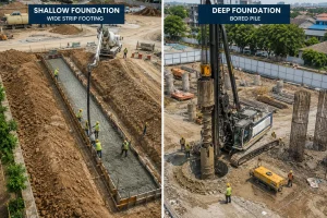
In all cases, the site conditions at the crane or lifting equipment positions, ground bearing capacity, access for heavy plant, headroom constraints, and proximity to existing structures or live traffic, must be assessed and planned for before construction begins. The foundation conditions beneath crane positions are a particular concern on bridge sites, where the ground has frequently been disturbed by pier and abutment construction, and where the interface between fill material and natural ground creates variable and sometimes unpredictable bearing conditions. An understanding of foundation types and their bearing characteristics, as covered in detail in the guide to types of pile foundation and when each is used, is directly relevant to the assessment of crane support conditions on bridge construction sites.
Maintenance and inspection of bridges in service requires working-at-height access to deck soffits, pier faces, arch ribs, cable anchorages, and truss members, often above water or in locations not reachable by ground-based equipment. Under-bridge inspection vehicles, bridge inspection units mounted on truck booms, and rope access techniques are all used for in-service bridge inspection, with the choice of access method determined by the bridge geometry, the access constraints, and the nature of the inspection being carried out.
For the full range of lifting and access equipment suited to civil construction and bridge work, including mobile cranes, crawler cranes, and aerial work platforms, the overview of construction equipment solutions for civil and infrastructure projects provides practical context for equipment selection at every project stage.
Also read : Boom Lift vs Cherry Picker: Key Differences Explained
The Right Equipment for Every Stage of Bridge Construction
Bridge construction is one of the most demanding categories of civil engineering work, structurally complex, logistically constrained, and dependent on lifting equipment that can perform reliably in difficult site conditions. Whether the project involves erecting precast beams on a motorway overpass, positioning arch rib segments across a river gorge, or installing cable stay anchors on a new harbour crossing, the choice of crane type, lifting configuration, and access equipment is a critical element of the construction plan.
RR Machinery provides a comprehensive range of construction and lifting equipment for sale and rental, including mobile cranes, crawler cranes, rough terrain equipment, boom lifts, and power generation solutions, all maintained to full operational standard and supported by experienced technical specialists. Explore our full range of heavy construction and lifting equipment solutions, or contact our team for practical advice and a clear quotation matched to the specific requirements of your bridge or civil infrastructure project.